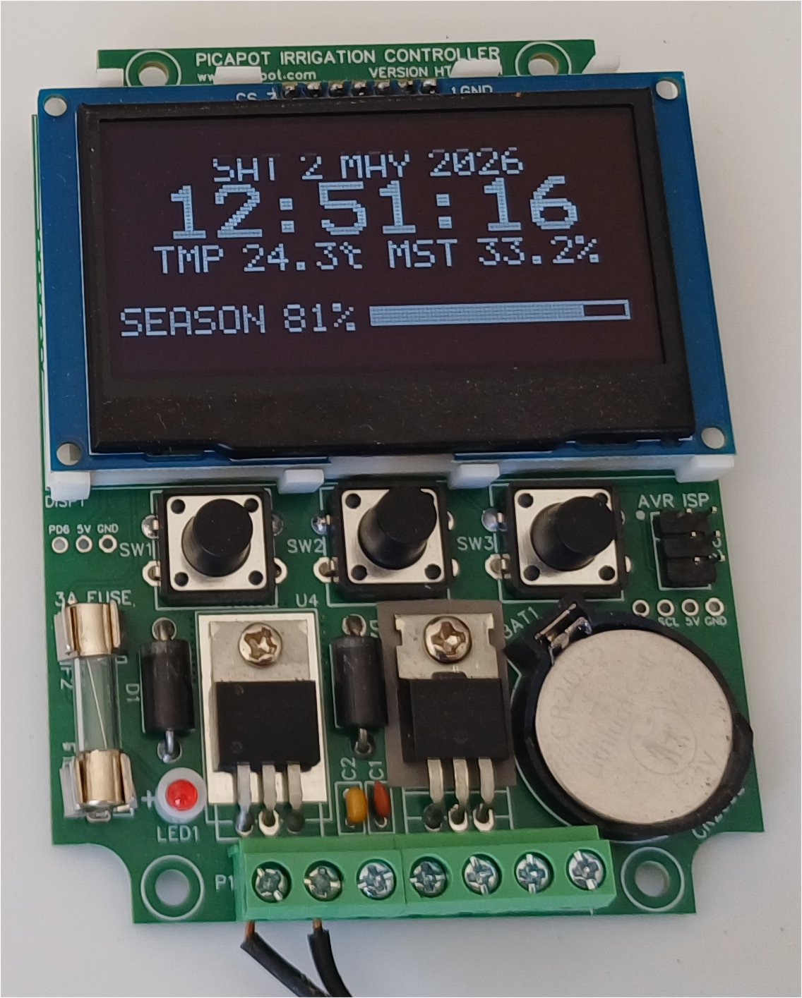
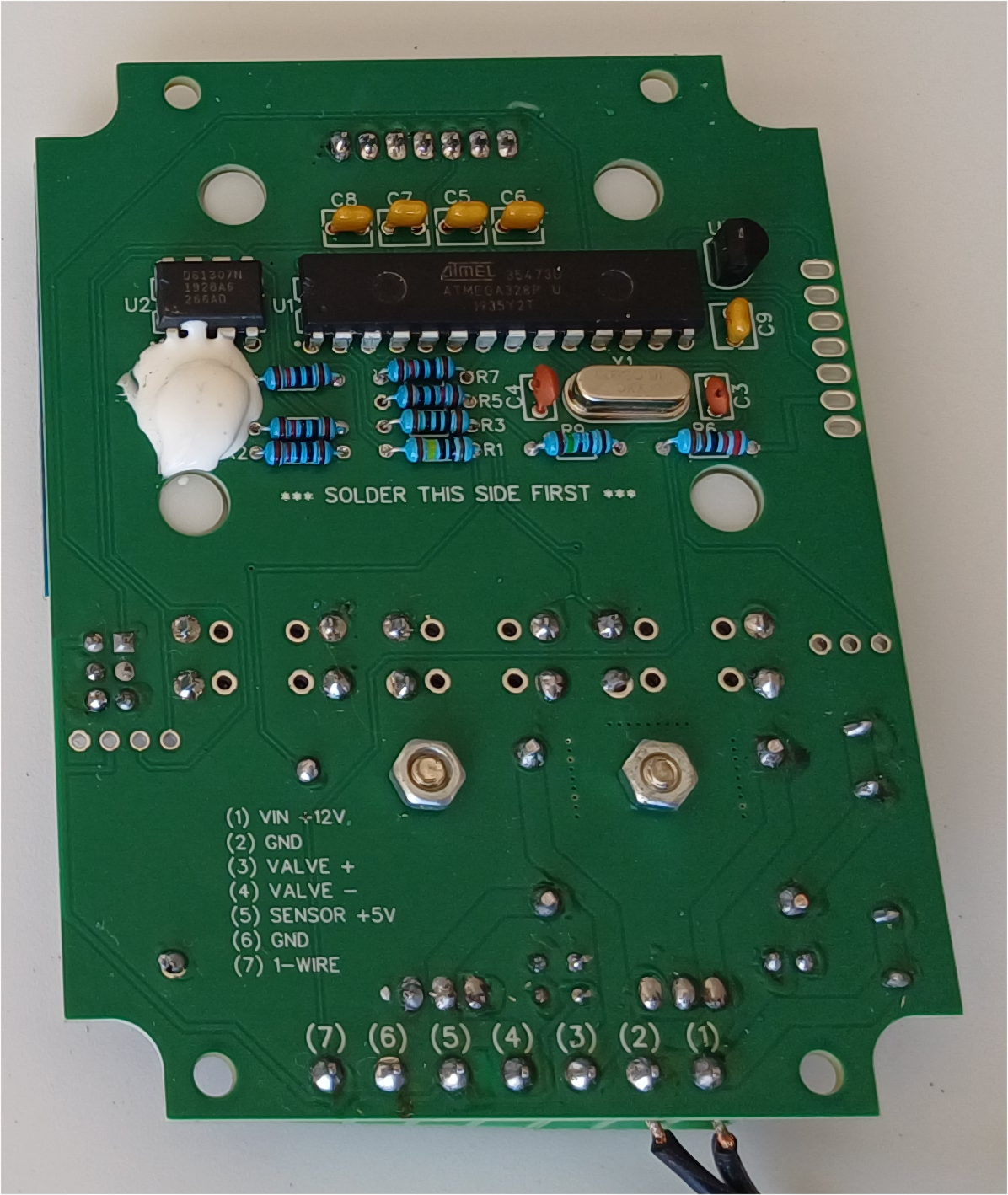
Controller Build
The first step is to get a controller PCB and solder the components onto it.
To purchase an industrial-quality copy of the PCB you have a few ways:
- Send the zipped Gerber file to your favorite PCB manufacturer. The PCB measures 96 x 72 mm.
- If you feel like posting a review of the project on this website, send me a message, and I'll ship you a PCB for free.
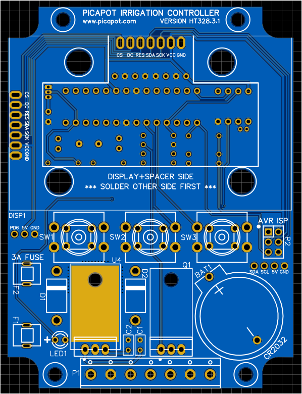
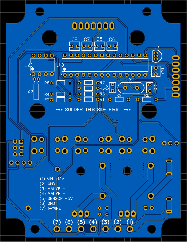
The PCB has components on both sides. The components on the back side, the one with the ATMEGA328P, must be necessarily soldered first.
You can get the full list of components from the BOM page.
You can modify the PCB Project if you agree with the GNU 3.0 License.
Display
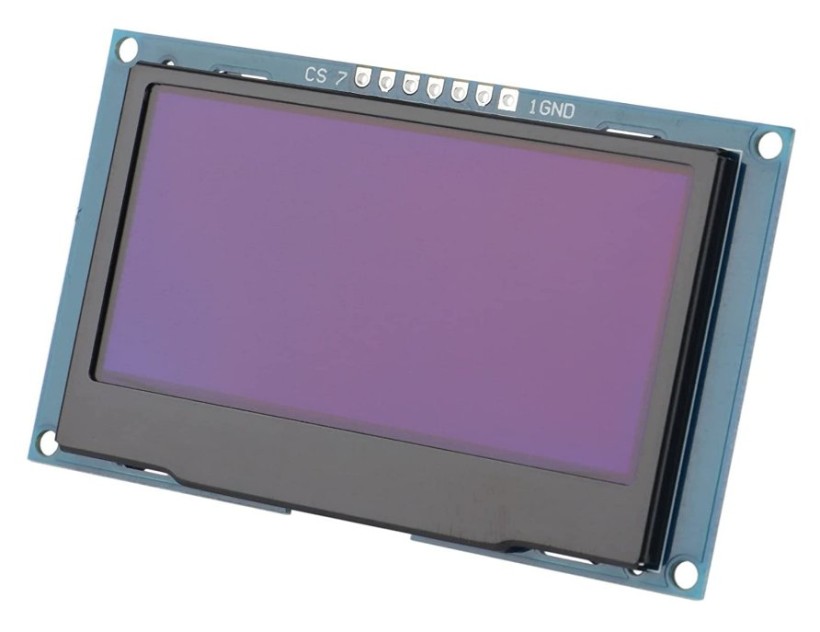
The controller interface consists of three push buttons and a 2.42-inch 128x64 OLED SPI display with a 7-pin connector.
There are two common versions of this display module: one with the connector pins on top, and one with the connector pins on the left side. Both can be used, but the spacer (see below) will fit only with the connectors on top.
These display modules normally work with SPI (default), but they can be configured to use I2C by tweaking a few components. In our case, we need the default SPI version.
Spacer
The display must be raised 5 mm from the PCB. The best way to do this is to use a 3D-printed spacer that keeps the display perfectly centered and at the correct distance.
Alternatively to the spacer, you can glue two 5 mm-thick plastic strips under the display's lateral sides.
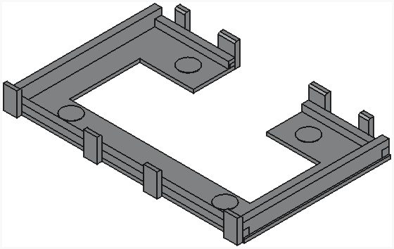
You can download the STL file to print the spacer from here.
When you receive the PCB for free, you will also receive the display spacer.