Controller Build Guide
The first step is to get a controller PCB and solder the components onto it.
To purchase an industrial-quality copy of the PCB, you can:
- Buy a PCB or a controller kit directly from me
- Send the zipped gerber file to your favourite PCB manufacturer. The PCB measures 96 x 72 x 1.6 mm
Important assembly note: The PCB has components on both sides; Solder the display (DISP1) as the last component.
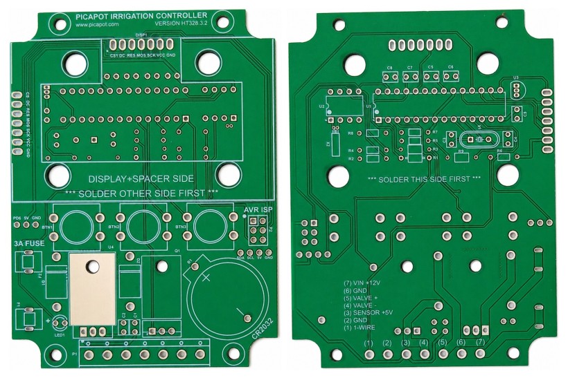
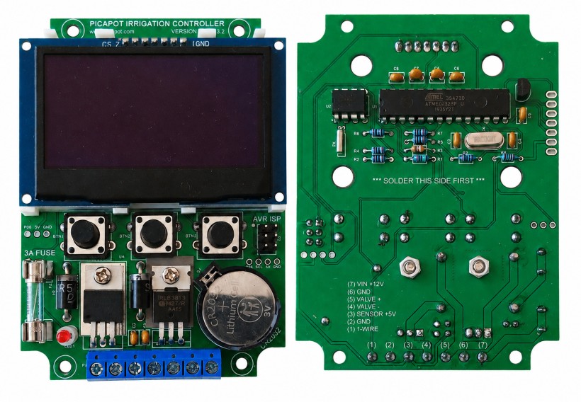
The controller project was created with EasyEDA Pro and can be modified and redistributed under the terms of the OCL v1.1 + GAtt v1 licence.
Components
All the components are pass-through. To help identify the components, most of them are linked to their LCSC or Mouser pages.
Designators in bold indicate components that must be inserted with the correct polarity/orientation (as marked on the PCB).
| Des. | Component | Qty | Notes |
|---|---|---|---|
| U1 | ATMEGA328P | 1 | The brain of the system. U1 and U2 must not be socketed; otherwise, the assembled PCB will not fit inside the enclosure. |
| U2 | DS1307 | 1 | Real-time clock with battery backup. |
| U3 | DS18B20 | 1 | 1-Wire Temperature sensor. If no external sensor is present, it serves as the system's reference temperature. Push the component down until it touches the PCB. |
| U4 | LM7805 | 1 | Voltage regulator. It provides 5 V to the logic. It must be firmly secured to the PCB using an M3 × 5 mm bolt and nut, ensuring good thermal and electrical contact between the 7805 back tab and the PCB ground plane. |
| X1 | Crystal 16Mhz 18pf | 1 | Heartbeat of the ATMega328P |
| X2 | Crystal 32768hz 12.5pf | 1 | Heartbeat of the DS1307N. The lower the ppm error, the more accurate the clock will be. This is the most delicate component of the control unit. It is recommended to seal it with a few drops of neutral silicone after soldering. |
| Q1 | IRLB3813PBF | 1 | Switches the solenoid valve on and off. Use any TO-220 N-channel MOSFET rated ≥30 V with low RDS(on) at VGS = 4.5–5 V. Secure it to the PCB with an M3 × 6 mm bolt and nut. An insulating pad must be placed between the tab and the PCB to ensure proper electrical isolation. |
| LED1 | 3mm Red Led | 1 | Blinks every second. It must be raised 6 mm above the PCB using a led spacer. |
| R1 | Resistor 2 MΩ 1/8W | 1 | Resistor for sensing the battery voltage. |
| R2, R4, R5, R7, R8 | Resistor 10 kΩ 1/8W | 5 | Pull-up resistors. |
| R3 | Resistor 300 Ω 1/8W | 1 | LED1 resistor. |
| R6 | Resistor 2.2 kΩ 1/8W | 1 | 1-wire sensor pullup. |
| R9 | Resistor 100 Ω 1/8W | 1 | Q1 gate resistor. |
| C1, C2, C5, C6, C7, C8, C9 | 100 nF Ceramic Capacitor 2.54mm pitch | 7 | Decoupling capacitors. |
| C3, C4 | 22 pF Ceramic Capacitor 2.54mm pitch | 2 | X1 Load capacitors. |
| D1, D2 | SCHOTTKY diode 40V 5A | 2 | Reverse current and valve flyback protection. If you don't need the reverse current protection, you can replace D1 with a piece of electric wire. |
| F1, F2 | 5x20 Fuse Clip 4.8mm pitch | 2 | Fuse holder. A 3A fuse is also required. |
| SW1, SW2, SW3 | Tactile Switch SPST 12x12x11mm | 3 | User interface buttons. Button height: 11 mm. |
| BAT1 | CR2032 battery holder | 1 | A CR2032 battery is also required. |
| DISP1 | 2.42'' OLED SPI display | 1 | A display spacer is also required. It is recommended to glue the spacer to both the PCB and the display to prevent vibrations. More info in the chapter below. |
| P1 | 7-position terminal block 5mm pitch | 1 | The terminal block height must be 10.5 mm or less, otherwise the enclosure cover will not close properly. |
| P2 | 2x3 pins male header 2.54mm pitch | 1 | AVR ISP programming port. |
Display
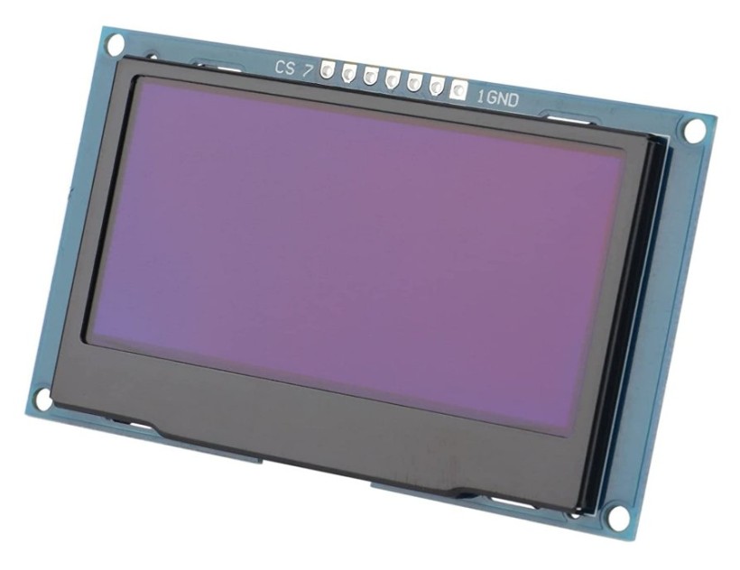
The controller interface consists of three push buttons and a 2.42-inch 128x64 OLED SPI display with a 7-pin connector.
There are two common versions of this display module: one with the connector pins on top, and one with the connector pins on the left side. Both can be used, but the spacer (see below) will fit only with the connectors on top.
These display modules normally work with SPI (default), but they can be configured to use I2C by tweaking a few components. In our case, we need the default SPI version.
Display Spacer
The display must be raised 5 mm from the PCB. The best way to do this is to use a 3D-printed spacer that keeps the display perfectly centered and at the correct distance.
controller_screen_spacer.stl (STL, 139.34 KB)
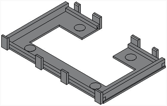
Alternatively to the spacer, you can glue two 5 mm-thick plastic strips under the display's lateral sides.
Firmware
Download and Upload Firmware
If you purchase a controller kit from me, the ATmega328P comes with the firmware already installed, so you can skip directly to the First Run section.
The source code, precompiled .hex file, build settings, and upload commands are available in the GitHub repository:
https://github.com/picapot/picapot-controller-328
First Run
During the first execution of the firmware, the controller scans the 1-Wire network to detect the internal DS18B20 temperature sensor and stores its address in EEPROM. It is important that no external sensors are connected at this stage; otherwise, the controller will not be able to distinguish between the internal (U3) and external sensors.