Components
Overview → PCB → Components → Sensor → Enclosure → Software → Valve → Installation
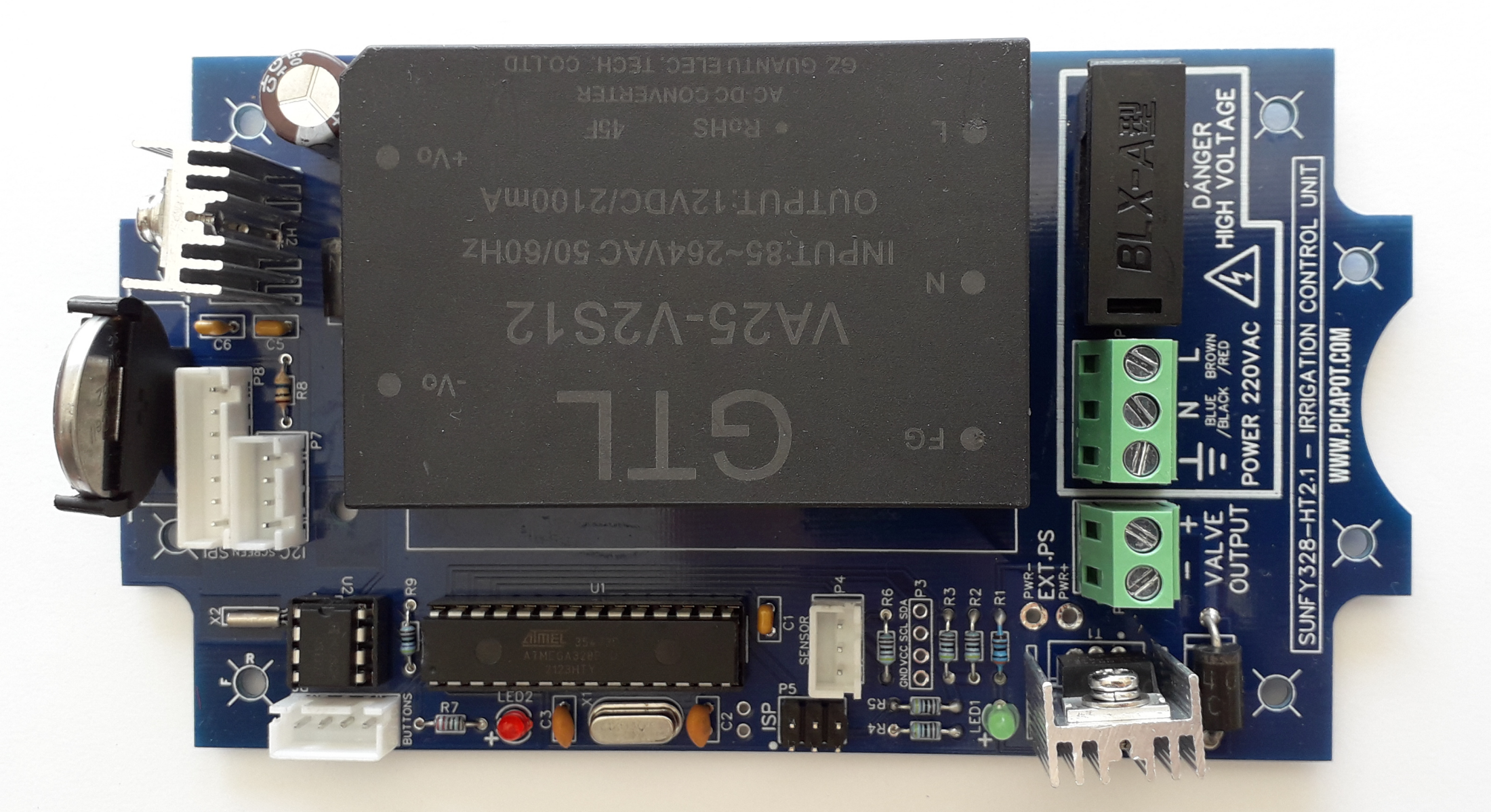
Control Unit Components
All the components are pass-through components, and they are soldered on the front side of the PCB.
To provide a better identification of the components, each one is linked to the respective page of LCSC, which is a global distributor of electronic components.
Designators in red are components which must be inserted with the correct polarity (marked on the PCB).
| Designator | Component | Qty | Notes |
|---|---|---|---|
| U1 | ATMega328P | 1 | Brain of the system. It is the same microcontroller used on the Arduino board. |
| U2 | DS1307N | 1 | Real-time clock and backup memory for the settings. |
| X1 | Crystal 16Mhz | 1 | Heartbeat of the ATMega328P |
| X2 | Crystal 32768hz 12.5pf | 1 | Heartbeat of the DS1307N. Lower is the ppm error of the component, more precise will be the clock. This is the most delicate component of the control unit. It is recommended to seal it, after soldering, with a few drops of silicone for electric components (neutral silicone or "704" silicone). |
| T1 | N-Channel Mosfet IRLB3813PBF | 1 | Used to switch on/off the solenoid valve. It can be replaced by several equivalent components listed below. |
| T2 | LM7805 | 1 | Voltage regulator. It gets 12V from the power module PS1, and provides 5V to the logic. |
| LED1 | Green Led 3mm | 1 | Switched ON during watering. |
| LED2 | Red Led 3mm | 1 | Blinks every second. |
| R1 | Resistor 3KOhm 1/8W | 1 | Resistor for LED1. |
| R2, R3, R4, R5, R6, R9 | Resistor 4.7KOhm 1/8W | 6 | Pull-up resistors. |
| R7 | Resistor 300Ohm 1/8W | 1 | Resistor for LED2. |
| R8 | Resistor 5MOhm 1/8W | 1 | Resistor for sensing the battery's voltage. |
| D1, D2 | Diode 1N5401 3A | 2 | Flyback protection diodes. |
| C1, C5, C6 | Ceramic Capacitor 100nF 2.54mm | 3 | Current stability. |
| C2, C3 | Ceramic Capacitor 22pF 2.54mm | 2 | Load capacitance for the crystal X1. |
| C4 | Electrolytic Capacitor 470uF 35V 10mm | 1 | PS1 output stability. |
| H1, H2 | Heat Sink 15*10.5*21 | 2 | Heatsinks for T1 and T2. |
| PS1 | Power Module 12V | 1 | System power supply. More info further below. |
| BAT1 | Vertical Battery Holder CR2032 | 1 | A CR2032 battery must be inserted into the holder and will keep time and settings during black-outs. |
| F1 | 5x20 Fuse holder | 1 | Overcurrent protection. A 2 Ampere fuse must be inserted into the holder. |
| P3 | Straight Square Pins 2.5mm 6mm (4pin) | 1 | I2C port (sensor). |
| P4 | XH 2.54 terminal (3pin) | 2 | 1-wire port (sensor). |
| P5 | Straight Square Pins 2.5mm 6mm (2x3pin) | 1 | ISP AVR programming port. The software is uploaded to the microcontroller using this port. |
| P6 | XH 2.54 terminal (4pin) | 1 | Three buttons connector (with common ground). |
| P8 | XH 2.54 terminal (7pin) | 1 | Port connector of the SPI display |
Optional Components
P1 and P2 are not needed if you decided to solder the terminals directly to the PCB.
| Designator | Component | Qty | Notes |
|---|---|---|---|
| P1 | Screw terminal 2 wires 5mm | 1 | Solenoid valve cable connector. You can use this screw terminal, or solder the 2 wires directly to the PCB. |
| P2 | Screw terminal 3 wires 5mm | 1 | VAC220 input cable connector. You can use this screw terminal, or solder the 3 wires directly to the PCB. |
| U1(socket) | IC socket 2x14 pins, 7.62 width | 1 | A socket will allow you to easily replace the IC, or to move it to another project. |
| U2(socket) | IC socket 2x4 pins, 7.62 width | 1 | A socket will allow you to easily replace the IC, or to move it to another project. |
| P7 | XH 2.54 terminal (4pin) | 1 | Port connector of the I2C display (not used in this project implementation) |
Equivalent Components
U1 can be replaced by the old version Atmega328.
U2 can be replaced by the equivalent Chinese clone.
T1 can be replaced by any TO220 N-Channel Mosfet with a Gate Threshold Voltage lower than 4V and a Drain-Source Voltage of at least 30V (WSR3090, IRLB4132PbF, NCE30H12, RU40120R).
T2 can be replaced by the equivalent Chinese clone.
All the resistors can be either 1/4W or 1/8W. R1 can be replaced by any value from 2.7 to 3.3KOhm. R2, R3, R4, R5, R6, R9 can be replaced by any value from 3.3 to 10KOhm. R7 can be replaced by any value from 220 to 470Ohm. R8 can be replaced by any value from 2 to 10MOhm.
P4, P5, P6, P7, P8 can be replaced by the common 2.54 straight square pins.
Power Module (PS1)
PS1 must output 12V which is the same working voltage of the solenoid valve. A power module with this form factor provides around 2-2.5 Ampere of current and it can provide a maximum of 25-30 Watt. Considering that the system and the screen consume around 2 Watt, 23-28 Watt remain available for the solenoid valve.
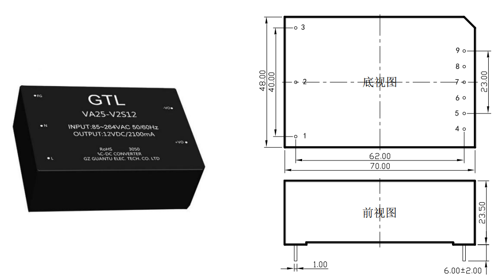
- TAS30-12-W (12 Volt 2.5A 30 Watt)
Equivalent Power Module
If you have a power module without the leads (picture), you can use it as an equivalent of the leaded PS1 following the advices listed below. The maximum dimensions (LxWxH) of the module are 8.5x5.8x3.5cm.
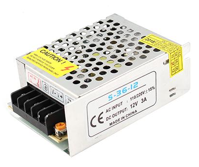
- Components PS1, P2, F1, D2, and C4 must not be soldered.
- Electrically insulate all the pads (top side) of components D2, C4 and PS1. Best way is to glue a 1mm silicone baking mat, or plastic sheet, to cover all the area of PS1, D2 and C4. The power module can be glued and/or bolted on top of the silicone mat.
- Connect the three wires of the VAC110/220 power cable connector to the power module (L N Gnd).
It is recommended to add a 2 Ampere wired fuse on the Live (L) wire.
ALWAYS DISCONNECT THE POWER CABLE FROM THE POWER GRID WHEN OPERATING ON THE PCB. - Connect with two wires (16-18 AWG) the output of the power module (V+ V-) to the port EXT.PS on the PCB. Mind the polarity marked on the PCB, because there is no reverse-polarity protection.
Front-end Components
The two components listed below must be soldered on the back side of the front-end PCB.
The display, the three buttons, and the cables are described in the enclosure page.
P1 and P2 can be replaced by the 2.54 shrouded square pins.
| Designator | Component | Qty | Notes |
|---|---|---|---|
| P1 | XH 2.54 terminal 90 degrees (7 pin) | 1 | Port connector of the SPI display. It will be connected to port P8 of the Control Unit. |
| P2 | XH 2.54 terminal 90 degrees (4 pin) | 1 | Port connector of the three buttons. It will be connected to port P6 of the Control Unit. |