Printed Circuit Boards
Overview → PCB → Components → Sensor → Enclosure → Software → Valve → Installation
Two printed circuit boards are needed in this project:
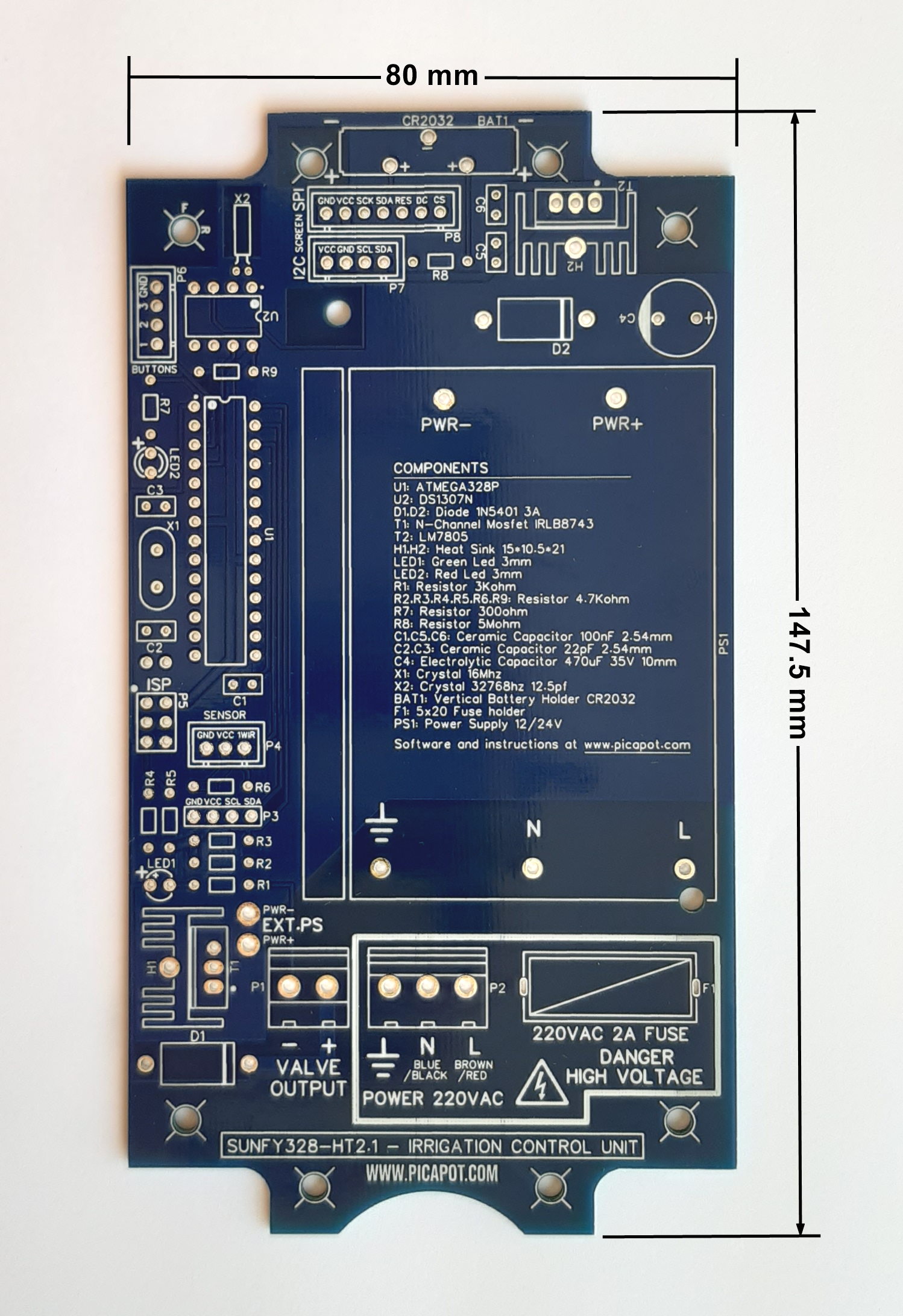
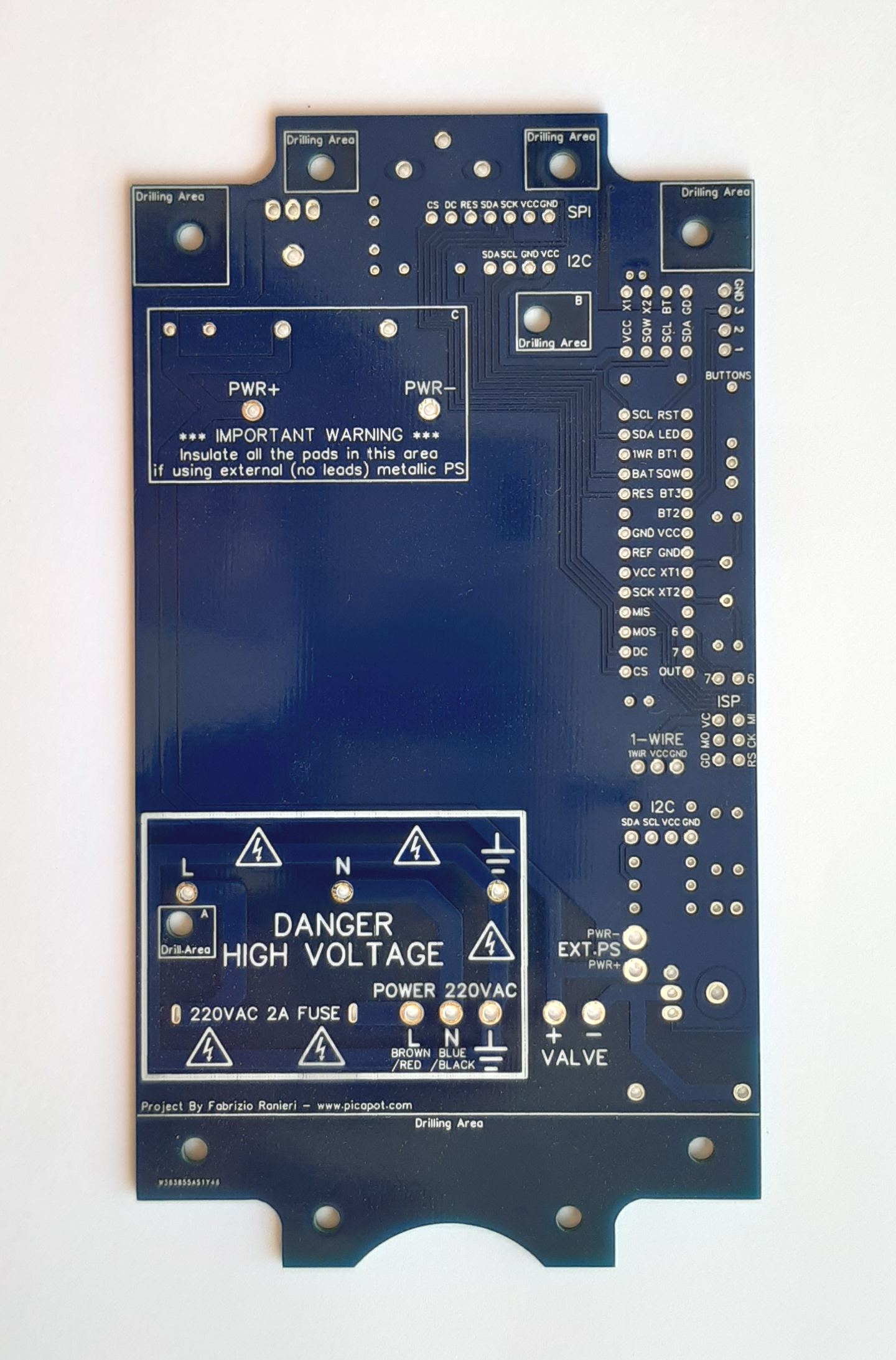
PCB 1 - Control Unit
This the core of the watering system, and when the components are soldered on, it is enclosed in a waterproof box.
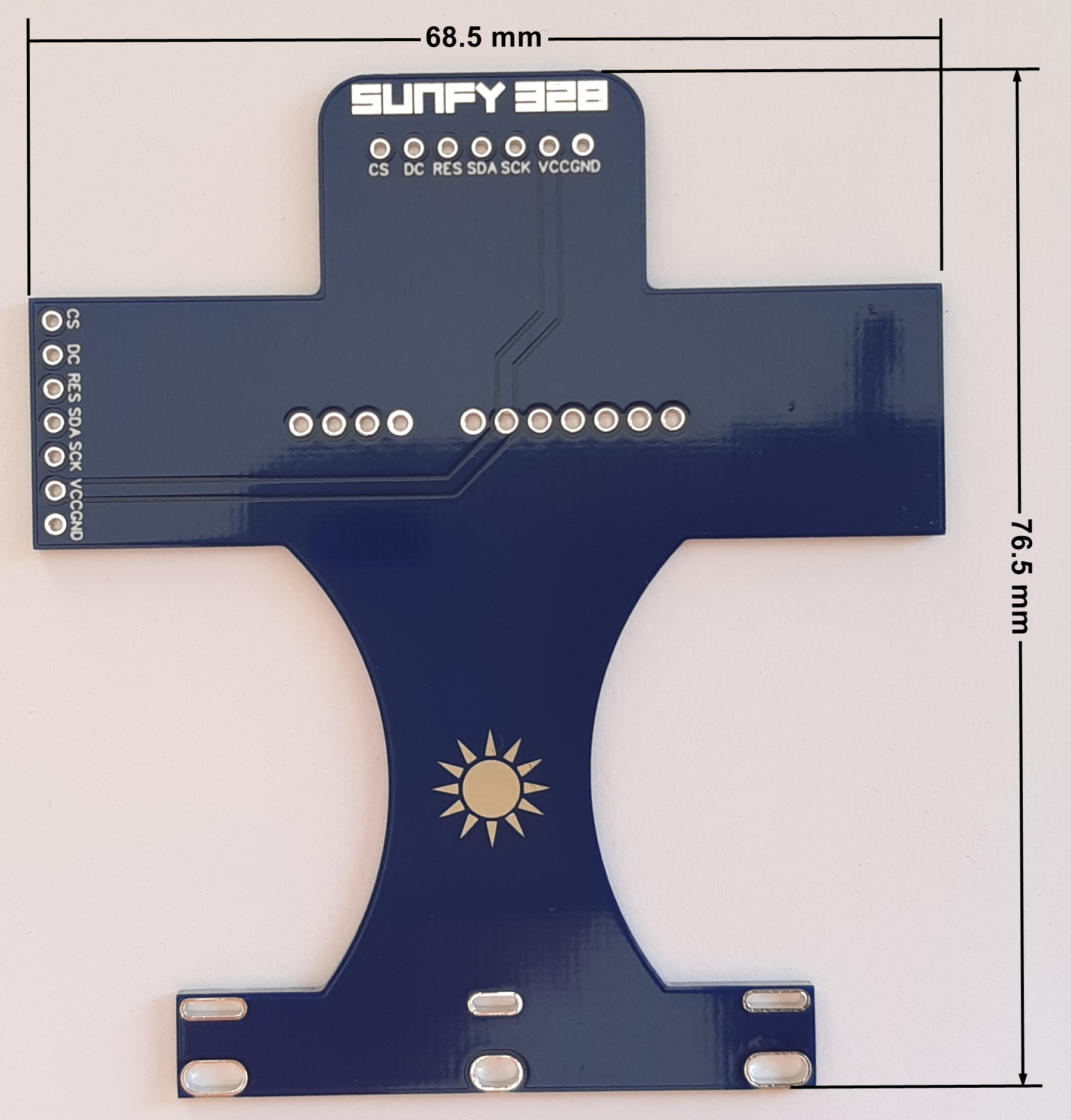
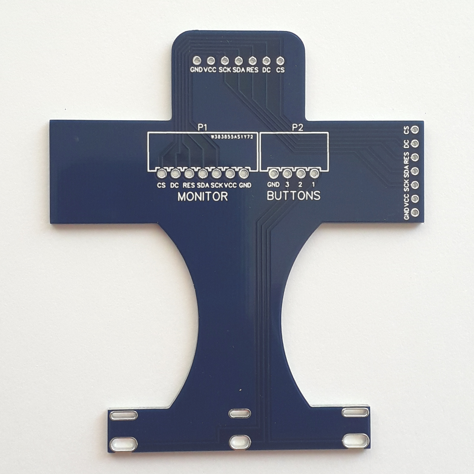
PCB 2 - Front-End
The Front-end PCB will keep in place the display and the three buttons, and connect them to the Control Unit.
Fabrication
To get an industrial quality copy of these PCBs, send the two zipped Gerber files to a PCB manufacturer.
Tested manufacturers:
The Control Unit PCB Project and the Front-End PCB Project are open source. You can modify and/or re-distribute them if you agree with the GNU 3.0 License.
Ports
The Control Unit has 9 ports, and the connections are explained in the enclosure page.
| Designator | Pins/Wires | Description |
|---|---|---|
| P1 | 2 | Solenoid valve (NC) cable connector |
| P2 | 3 | VAC220 power cable connector |
| P3 | 4 | I2C port A (normally used to connect a sensor) |
| P4 | 3 | 1-Wire port (normally used to connect a sensor) |
| P5 | 6 | ISP programming port |
| P6 | 4 | 3 buttons interface connector (3 wires + common GND) |
| P7 | 4 | I2C port B (used to connect a I2C display or a sensor, please note that GND and VCC positions are inverted compared to P3) |
| P8 | 7 | SPI display port |
| EXT.PS | 2 | External 12V power supply connector |