Enclosure
Overview → PCB → Components → Sensor → Enclosure → Software → Valve → Installation
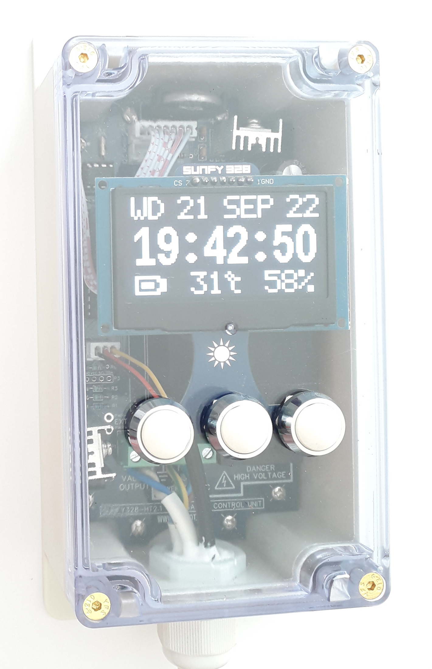
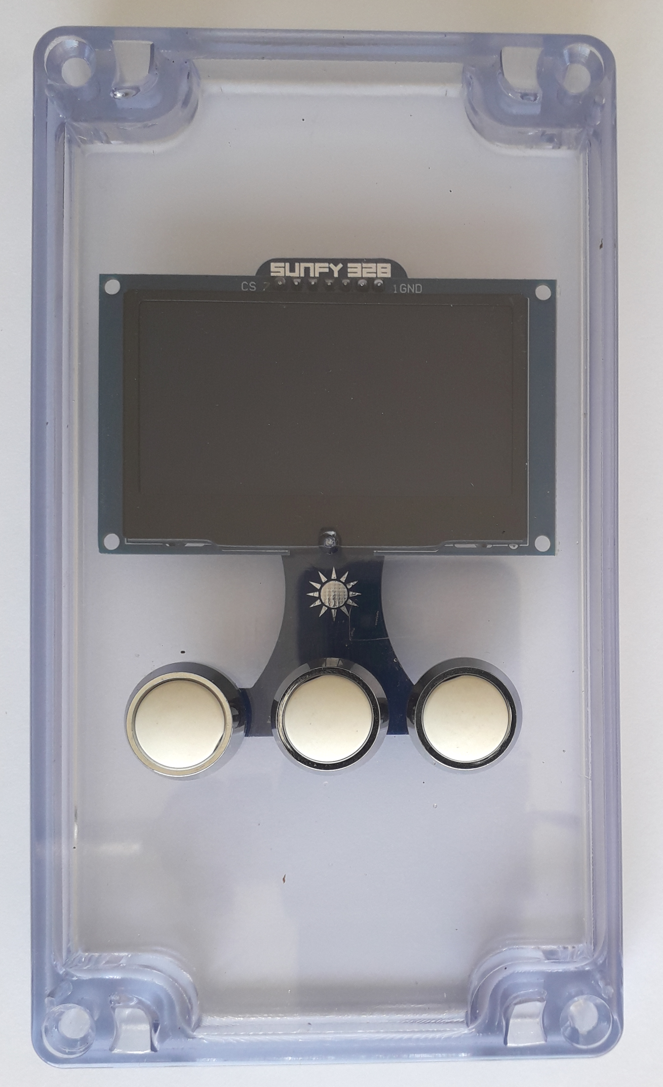
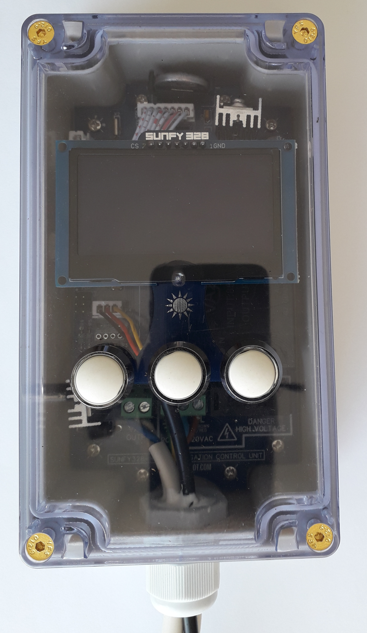
Sunfy328 is enclosed in a waterproof box for outdoor installations with a transparent top.
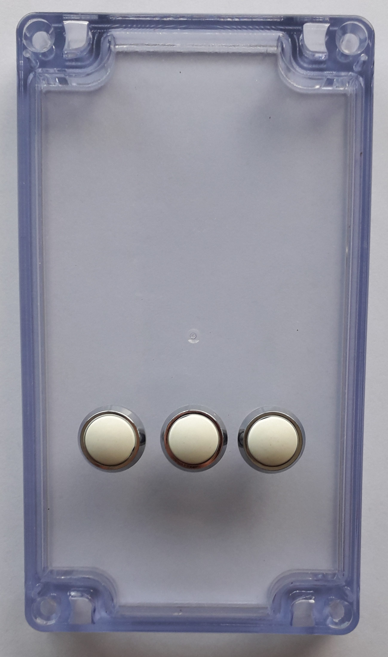
The user interface is made by a display 128x64 and three push buttons.
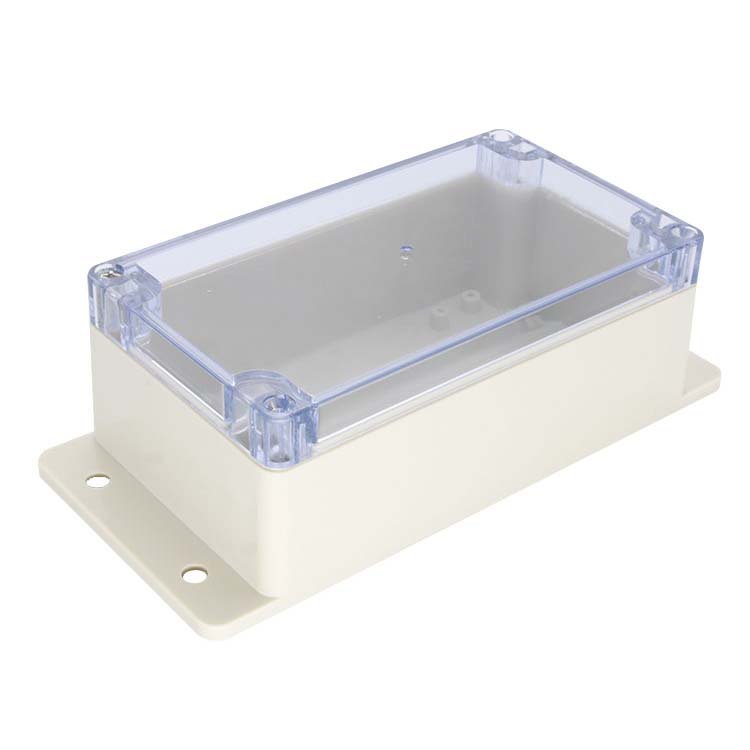
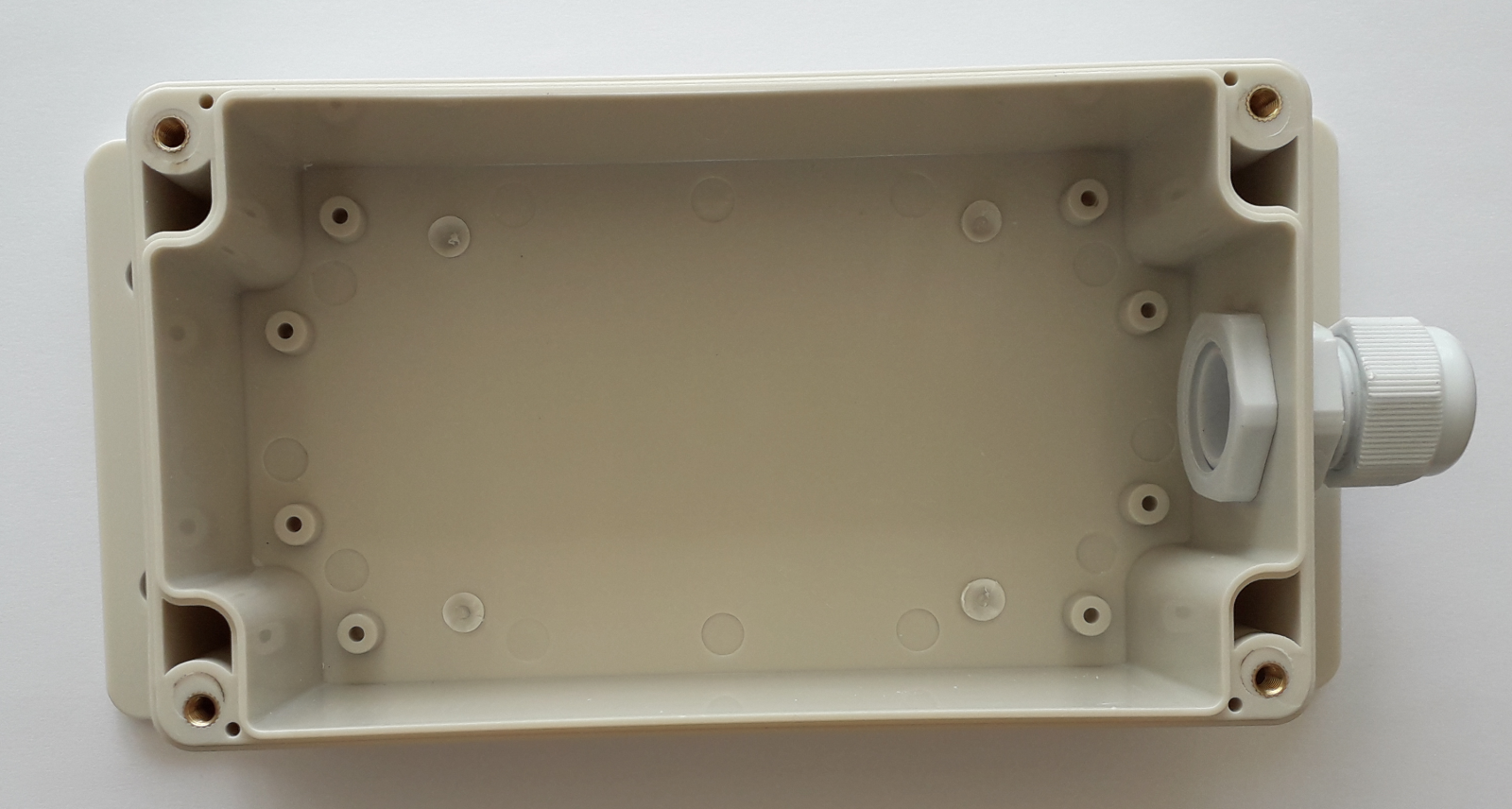
The external box dimensions are 90 x 195 x 60 millimeters (W x L x H) including the two fringes to secure the box to the wall. This box is quite easy to find and it is produced, in almost identical sizes and shapes, by several manufacturers.
You can buy the same exact box used in this project (model HT-22) directly from the manufacturer. The minimum order quantity is just 1 piece.
Bottom Part Preparation
If present, remove the 4 higher central screw bosses from the bottom part of the box. A fast solution is to reduce them with an 8 mm drill bit for metal, keeping attention to not damaging the bottom wall of the box.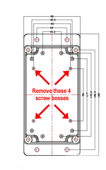
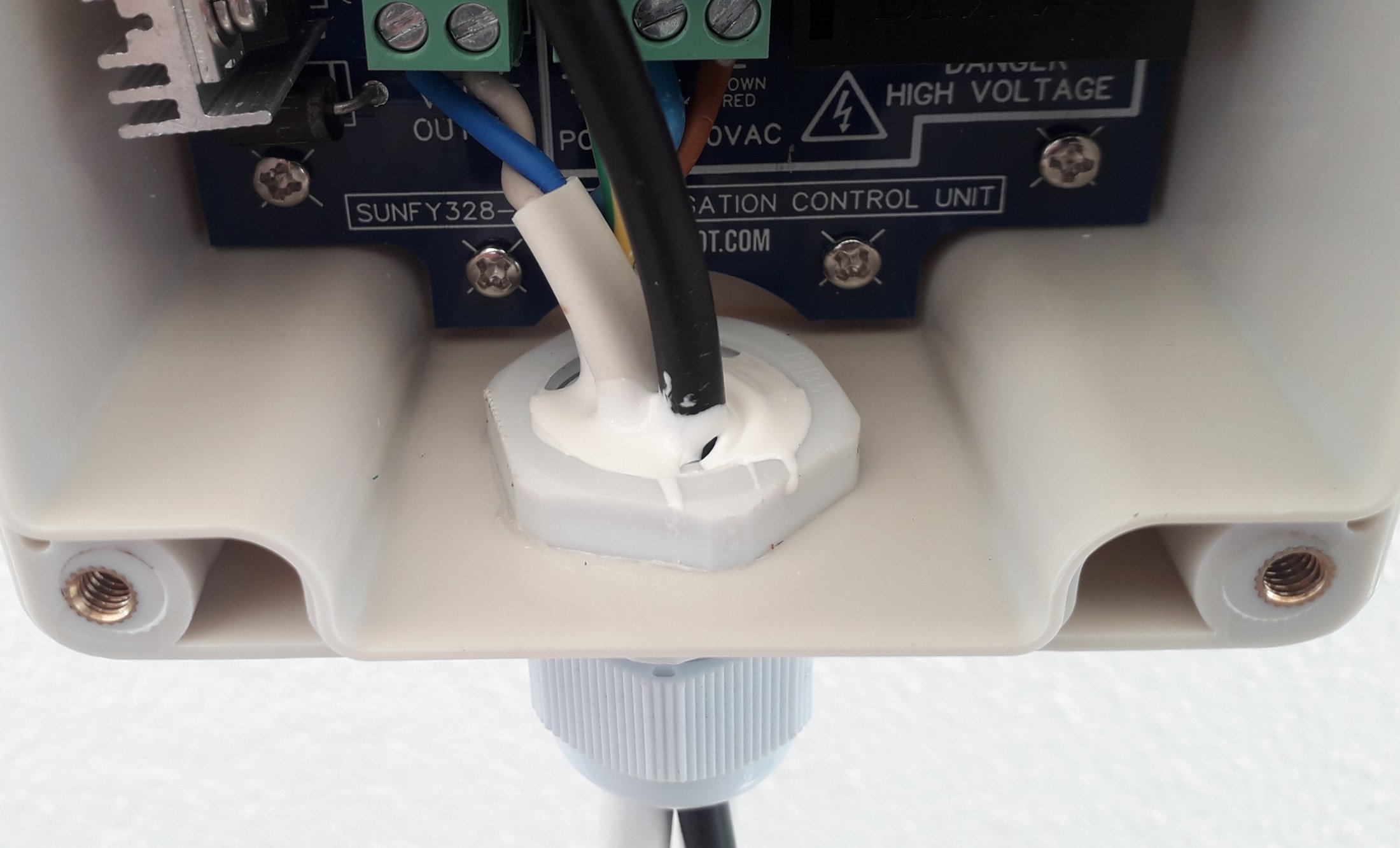
In the middle of one of the short sides of the bottom, make a hole with a diameter of 20 mm.
Bolt a waterproof white cable gland Pg13.5 / M20 throughout the hole. Use an o-ring gasket to externally seal the gland, and internally some glue to keep the nut in place.
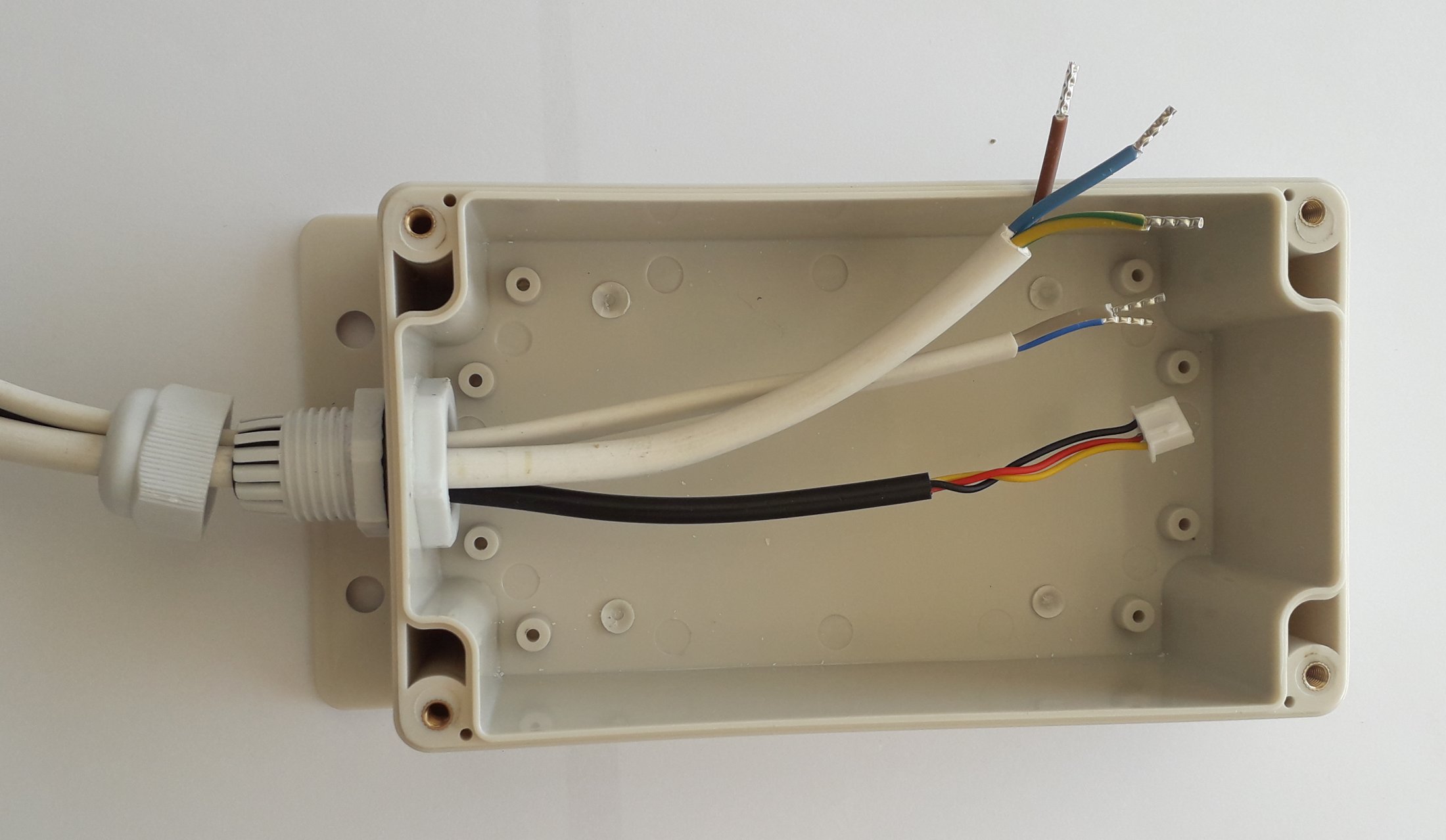
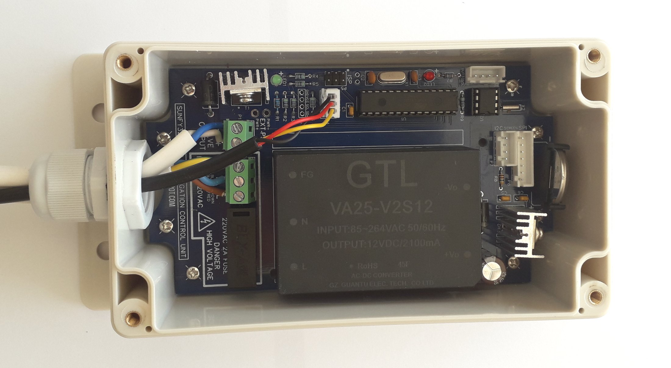
Pass the 3 cables of Sunfy328 through the cable gland and connect them to the PCB.
ALWAYS DISCONNECT THE POWER CABLE FROM THE POWER GRID WHEN OPERATING ON THE PCB.
3 cores 18-21AWG (0.50/0.80 sq mm) connected to port P2.
- L - Live (brown)
- N - Neutral (blue)
- GND - Ground (yellow/green)
2 cores 18-21AWG (0.50/0.80 sq mm) connected to port P1. Standard solenoid (NC) valves have no polarity, so you can connect the wires in both ways.
- V+ Positive (red/brown)
- V- Negative (black/blue)
The number of cores depends on the communication protocol used by the sensor: I2C sensors use 4 cores and they are connected to port P3 or P7, 1-Wire sensors use 3 cores and they are connected to port P4.
- +5V (red)
- GND (black)
- 1-WIRE/SCL
- SDA
The length of the cables depends on the distance of water (valve), electricity, and sensor from where the control unit will be installed. You can decide to keep them short and extend them during the installation, or better to keep them longer and reduce them later. If you don't know yet the distances, you can keep them 3.0 meters in length, which allows an easy installation in most of the locations.
To be compliant with the common security regulations, the terminals must be clamped in a ferrule before beying screwed to the PCB. As an alternative compliant solution, you can solder the terminals directly to the PCB (without using the ferrules and the components P1 and P2).
Secure the PCB to the bottom using eight M3 screws (6-8 mm length).
Arrange the cables inside the box, and tightly screw the external bolt of the cable gland.
Cut a 5x5 cm piece of plastic bag (or a small piece of plastic sponge) and push it into the cable gland till the bottom. This will prevent the silicone from dripping out.
Fill the remaining internal space of the cable gland with silicone (or "704").
Transparent Top Preparation
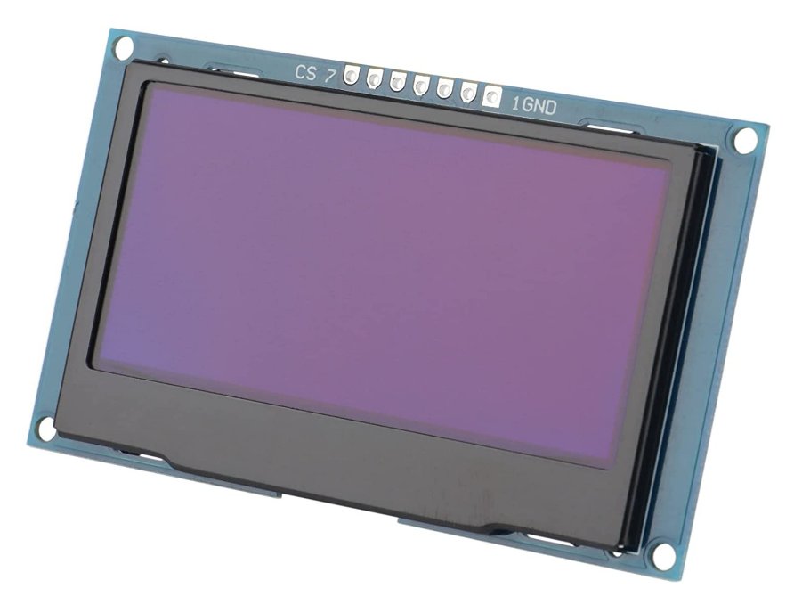
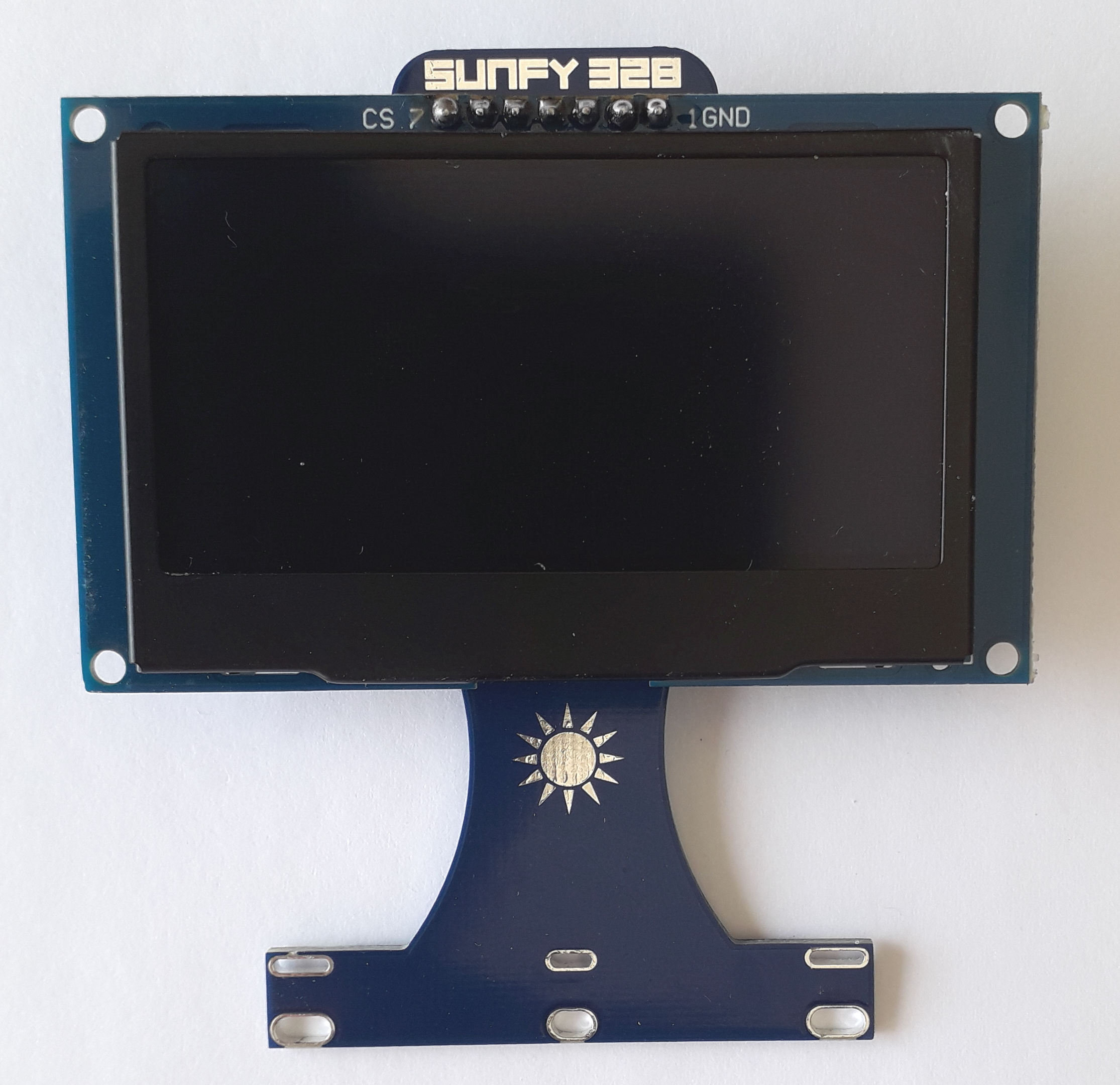
In this project implementation we are using a 2.42 Inches 128x64 OLED display SPI with a 7 pin connector.There are two common versions of this display module: one with the connector pins on top, and one with the connector pins on the left side. Both of them can be used, but the one with top connectors is preferred for the final aesthetic result. These display modules normally work with SPI (default) but they can be switched to work with I2C by tweaking some components. In our case, we need the default SPI version.
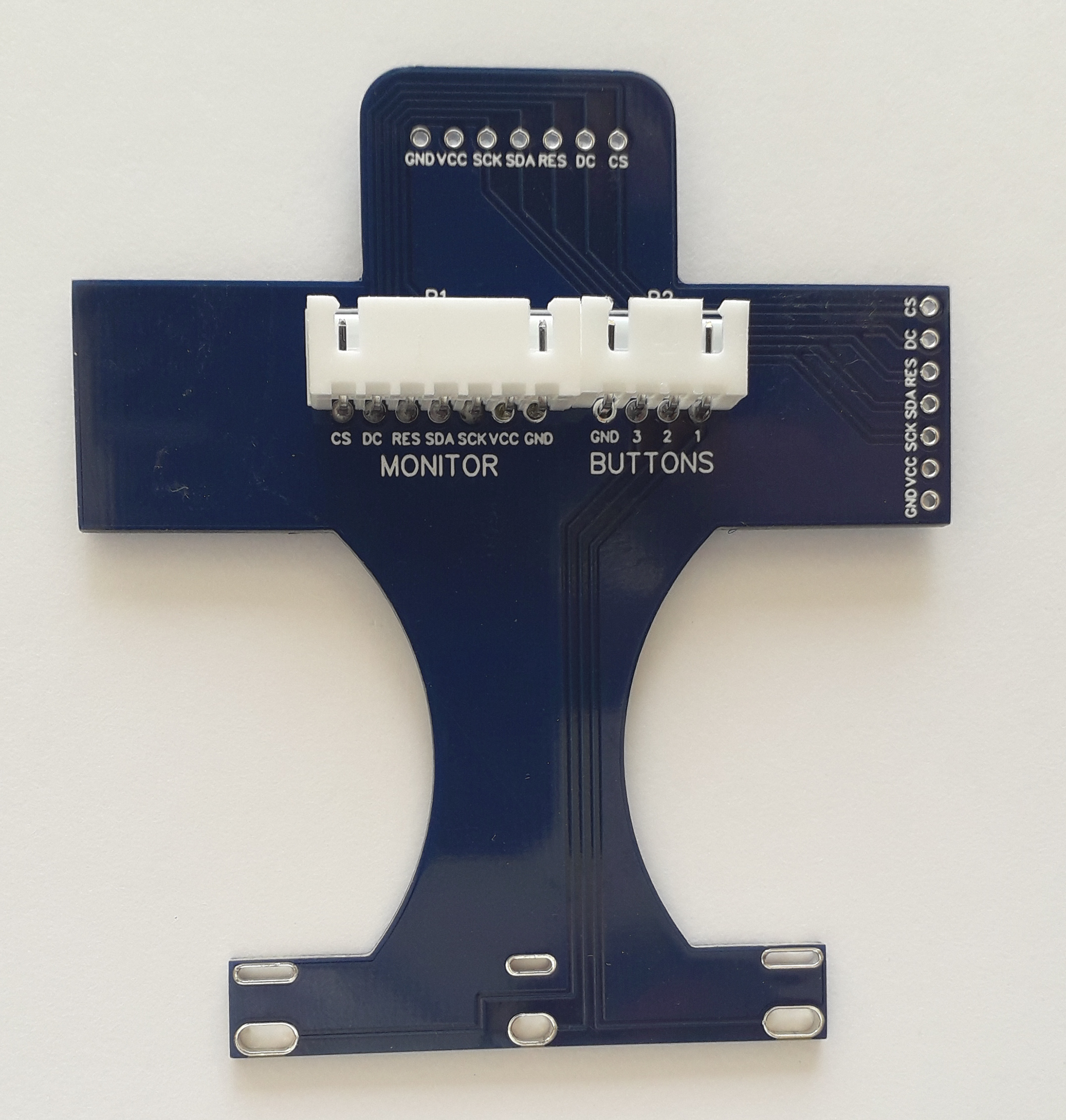
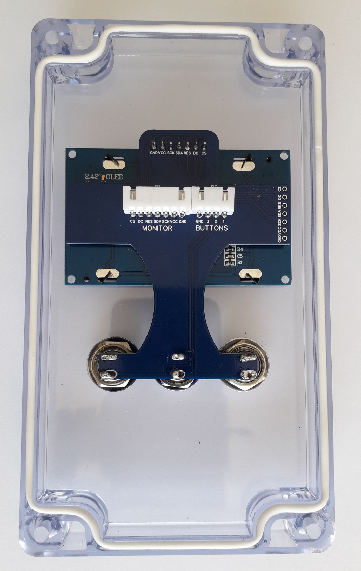
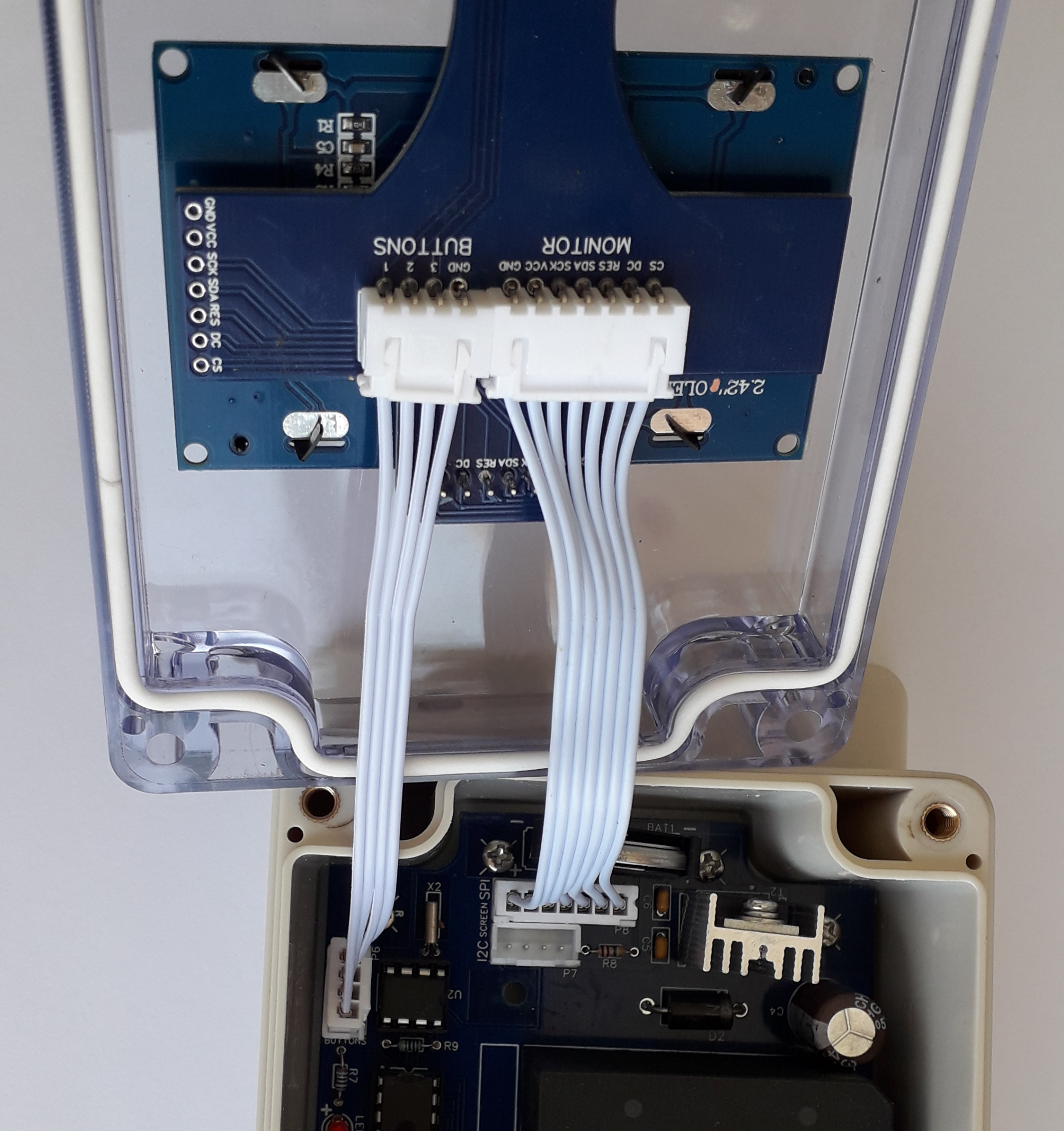
The display is visible through the transparent top of the box and it is kept in place by the Front-end PCB.
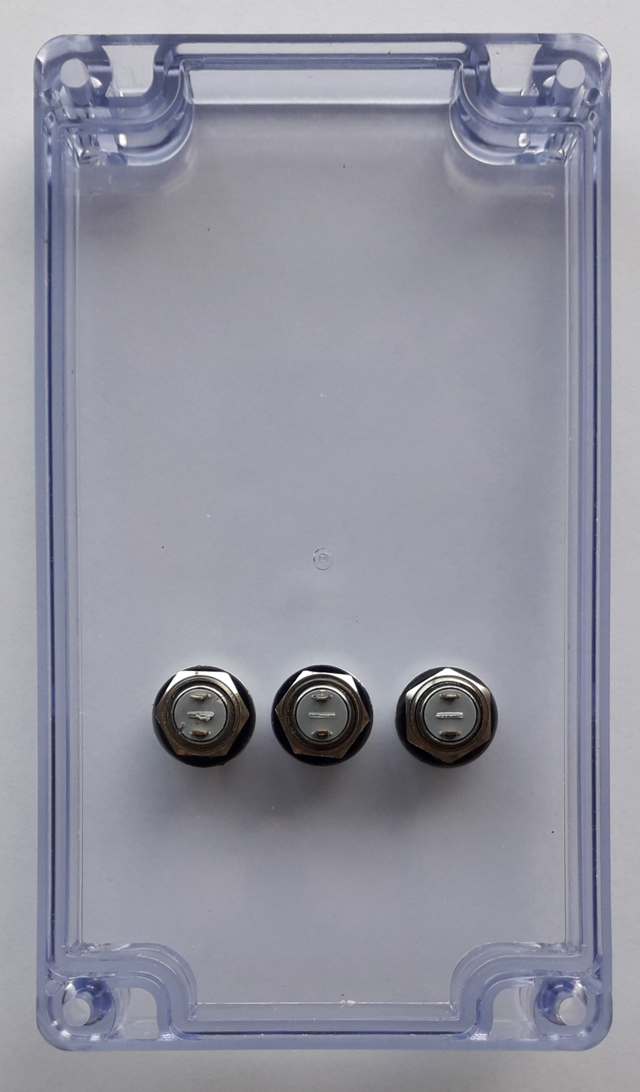
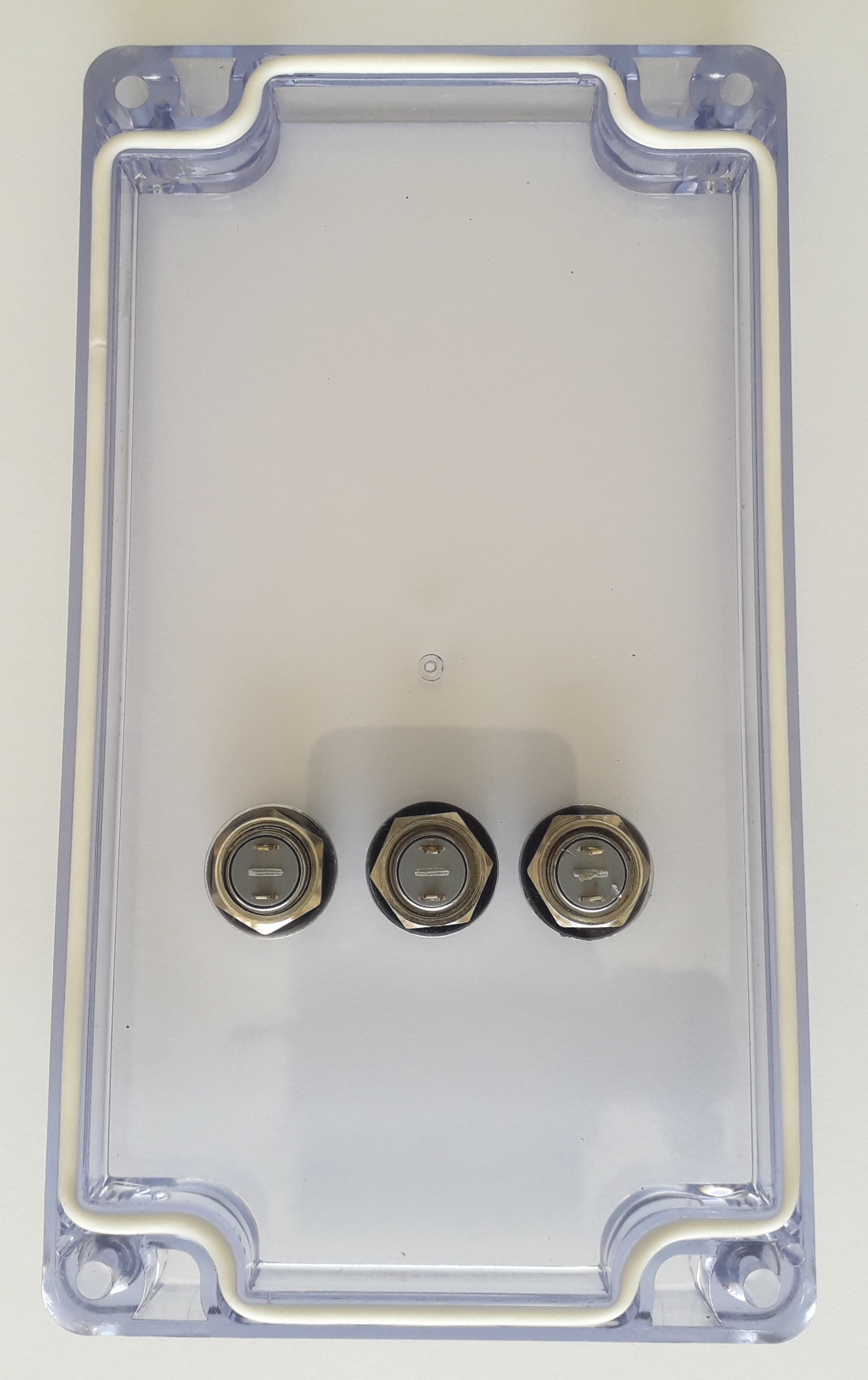
The Front-end PCB is secured to the top of the box with three buttons.
There are two models of button which are compatible with the front-end PCB:
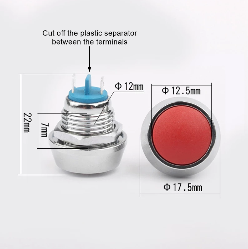
- Metallic waterproof 12 mm SPST button with 2 welding terminals
Their metallic body allows you to tighten the nut very well and squeeze the O-ring gasket that you must place between the button and the top. You can buy them from here, be sure to buy the model with "welding feet". The plastic separator between the two terminals must be removed. In this project we are using the white color, of course feel free to choose whatever color you like.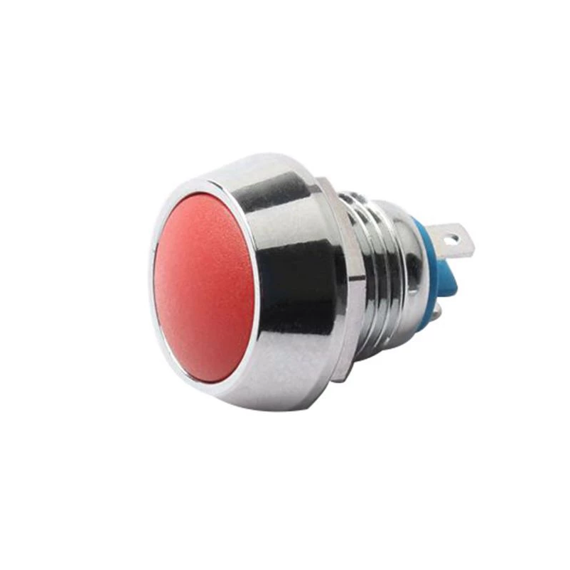
- Plastic waterproof 12 mm SPST button with 2 welding terminals
This is the model used in the first Sunfy328 projects. They are cheap and easy to find because sold by several sellers, but their plastic body doesn't allow to tighten the nut, and it is needed an extra work of potting to make the buttons steady and the holes waterproof.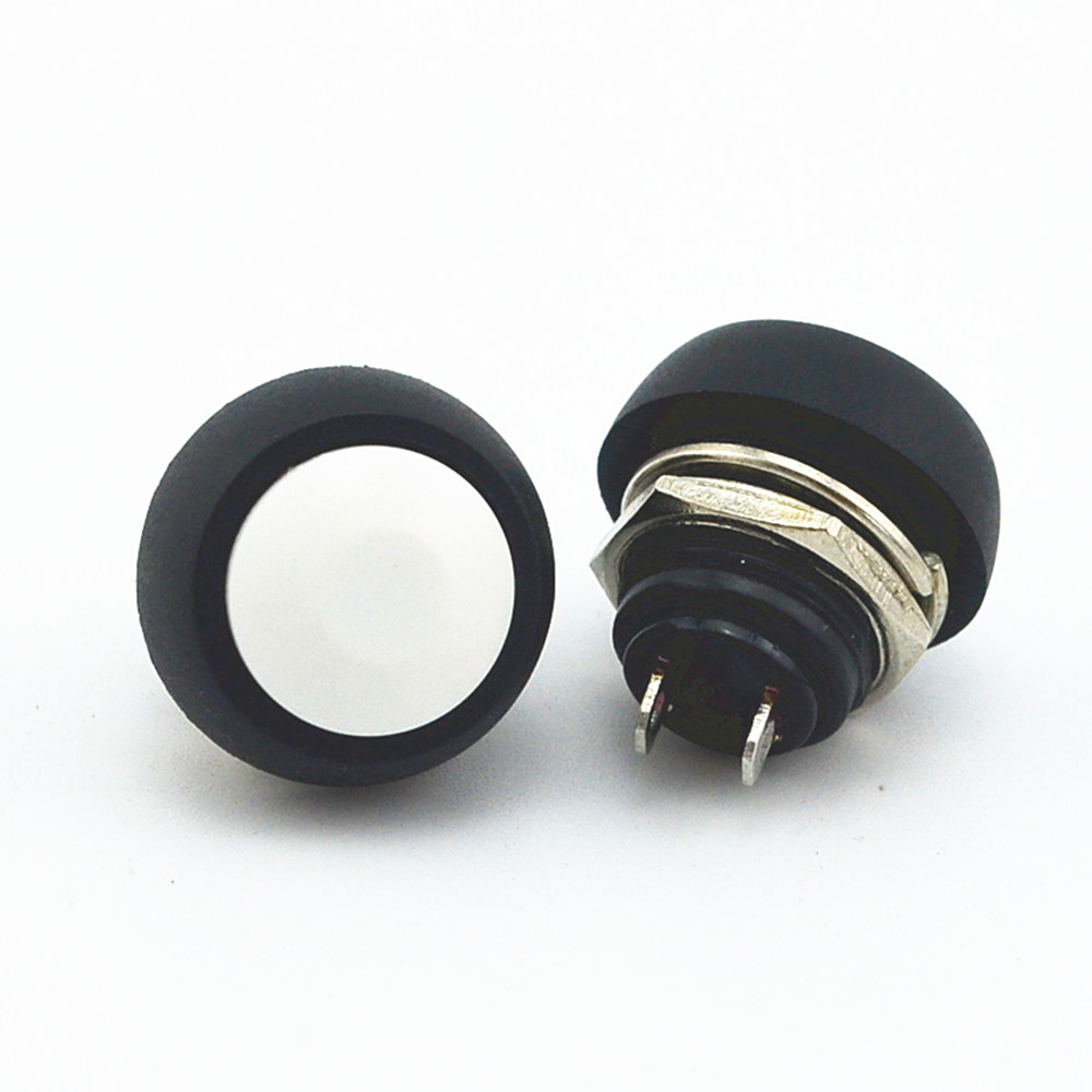
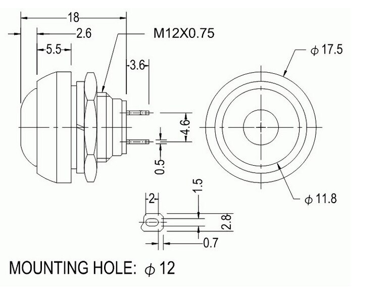
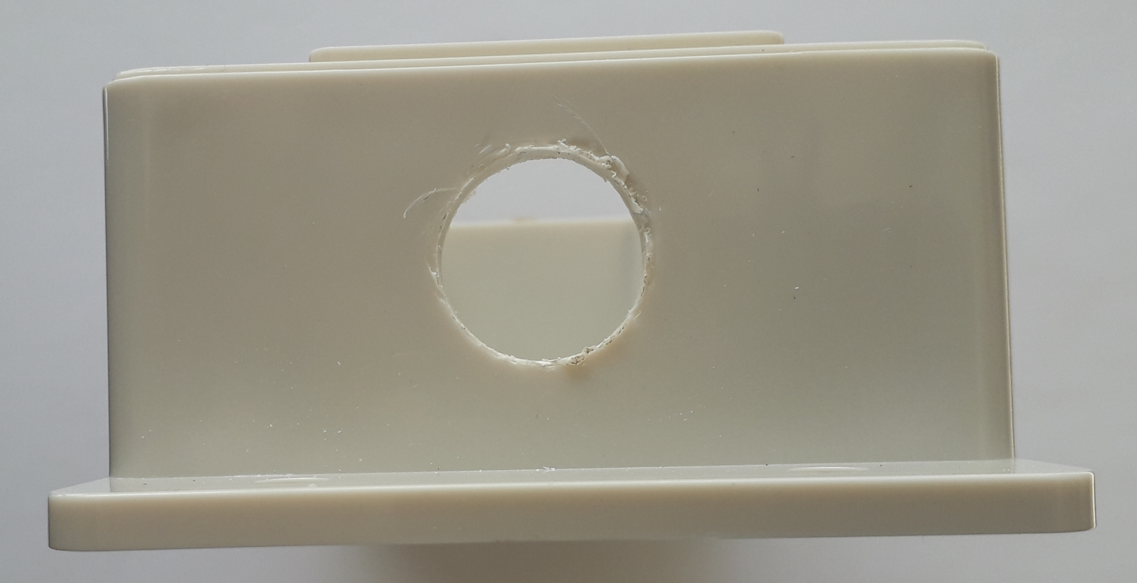
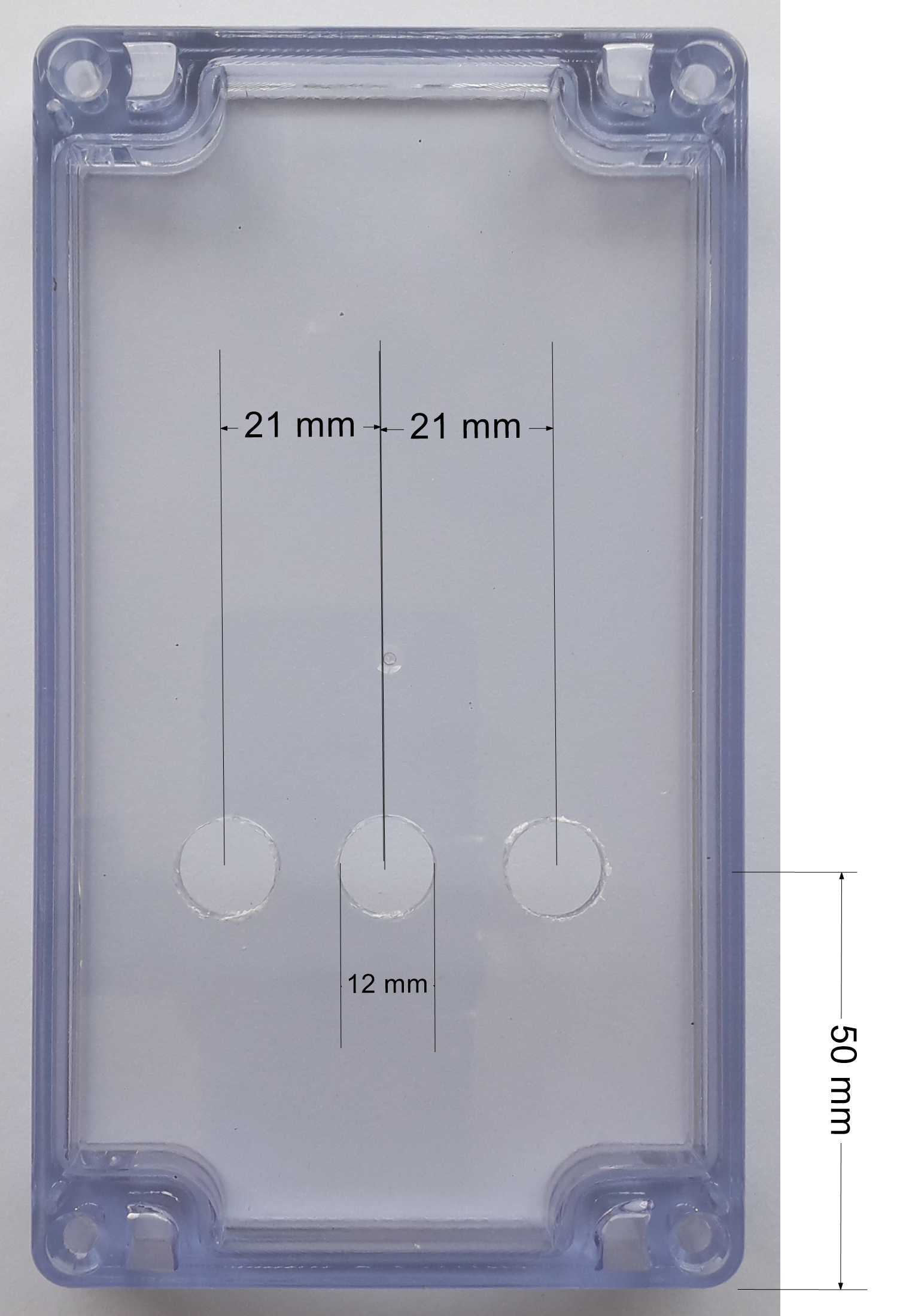
Using a 12 mm spade drill bit (with no self-feeding threaded tip), make three holes on the transparent top following the schema in the picture. Do NOT use a normal drill bit because you risk to crack the top!
Bolt the three buttons, using O-ring gaskets to externally seal the buttons.
The six terminals of the buttons must be aligned: you can use the Front-end PCB to keep them in the correct position while you finish to tighten the nuts.
Solder the two components P1 and P2 on the back side of the Front-end PCB.
On the front side of the PCB, insulate the solderings you have just done with 5 layers of standard electrical tape (0.2mm thick). The 5 layers are needed also to keep the display parallel to the PCB.
Solder the display on the front side of the PCB, using the 7x 2.54 straight square pin connector, provided together with the display.
Insert the silicone rope, provided together with the box, all around the nick present on the transparent top.
Remove the protection film from the screen of the display, and solder the PCB to the six buttons' terminals.
Finalize
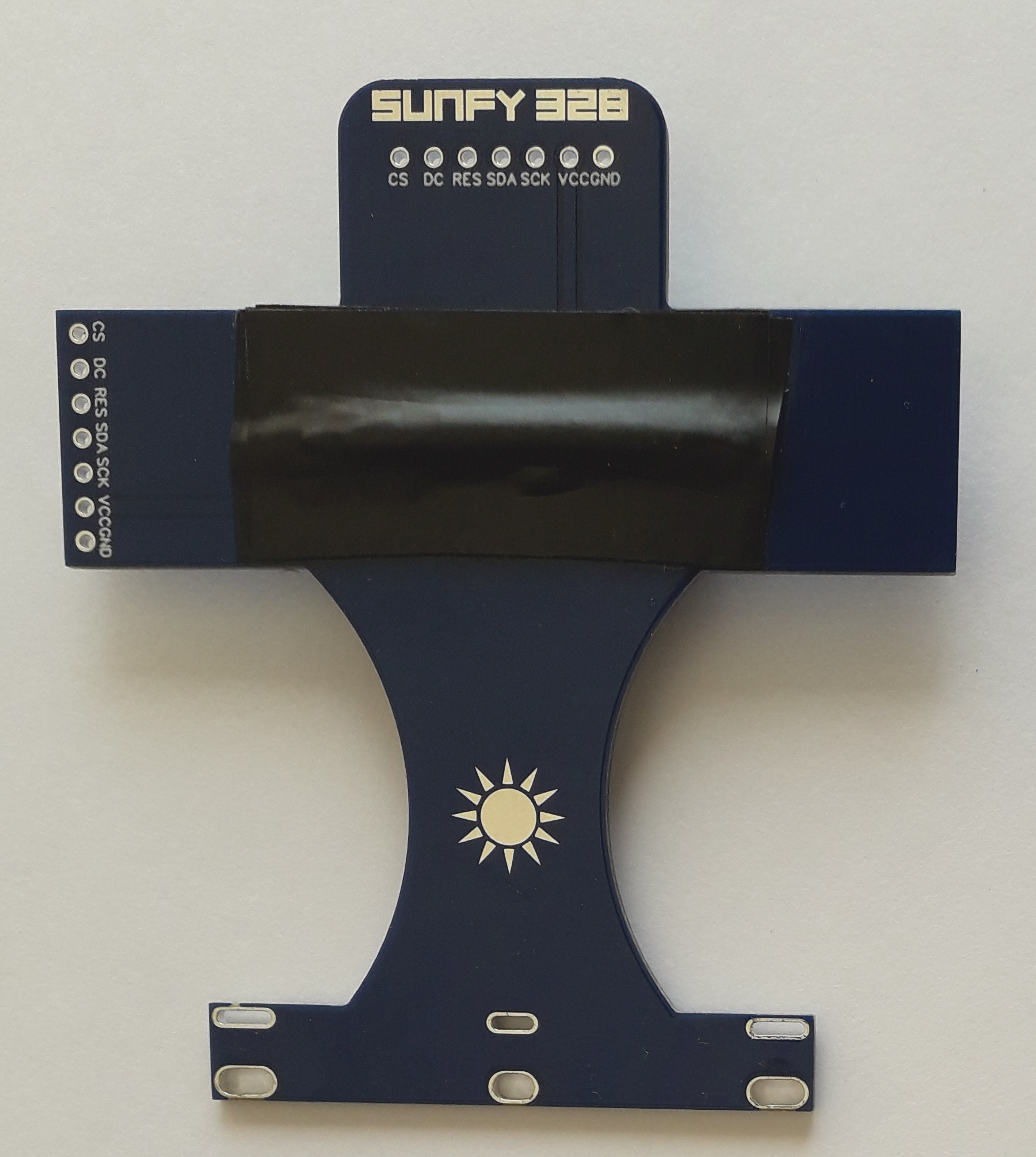
Upload the software to the Control Unit.Connect the Front-end with the Control Unit using two JST XH cables 10-20 cm length:
- 4 cores JST XH cable 2.54mm pitch single-row male-to-male (port P3 - buttons)
- 7 cores JST XH cable 2.54mm pitch single-row male-to-male (port P7 - screen)
If the Control Unit will be exposed to the weather, it is adviced to replace the four bolts provided together with the box, with titanium ones (M4 30mm), because in 10 years you will need to unscrew them to change the battery.