Sensor Build Guide
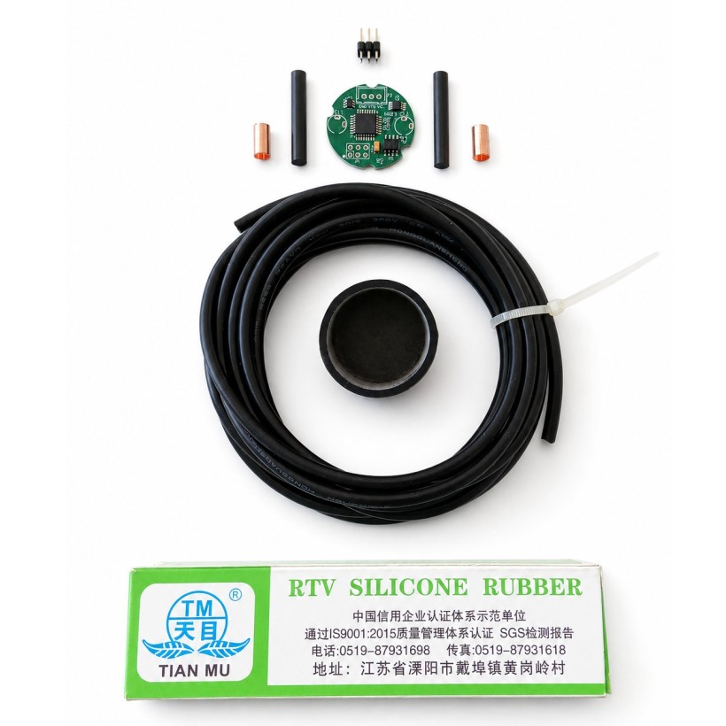
The PS100 sensor adopts SMD components and uses two special clips to hold the carbon fiber probes in place.
All the information needed to make the PCB and clips is provided below, but for a quicker and easier start, a kit is available with a pre-soldered, pre-programmed PCB and the components needed to complete the sensor.
Assembly Instructions
Step 1 — Calibrate and Upload the Firmware
If you bought the PS100 kit, you can skip this step because the firmware has already been uploaded and the sensor has already been calibrated.
The main purpose of the calibration is to compensate for the tolerance (10%) of the tantalum capacitor used by the sensor to measure humidity.
A .bat file and a precompiled .hex file are included in the repository for calibration and direct upload to the microcontroller via the ISP port P1. During the calibration process, the two probes must be connected together through a 10 kΩ resistor.
If you are using a different programmer from the AVRISP mkII, update the programmer ID in the commands accordingly.
Source code: https://github.com/Picapot/picapot-sensor-ps100
Step 2 — Solder the Clips and Cable
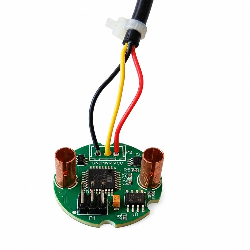
Solder the two clips and the cable to the top side of the PCB (see picture). The three wires of the cable, GND (black), 1WIRE (yellow or white), and VCC (red), must be soldered to the corresponding pads marked on the PCB.
Secure a cable tie at the end of the cable's insulating section, then trim the excess. It will act as a cable strain relief once the sensor is potted.
If you have a pre-programmed PCB, you can skip soldering the P1 header.
Step 3 — Install the Probes
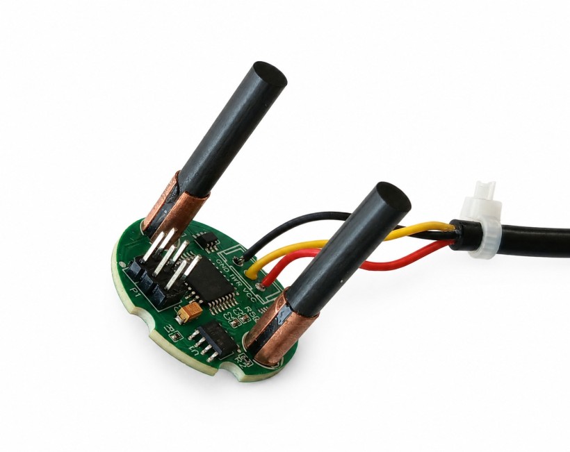
Insert the two carbon fiber probes until they touch the bottom of the PCB. Add a small drop of super glue to one corner of the clip, then rotate the probe by about 15–20 degrees so that the glue spreads between the clip and the probe. Repeat the operation on the other clip.
The clip must remain in electrical contact with the probe, so the glue must cover only a small portion of the probe.
Step 4 — Final Test
Before permanently potting the sensor, perform a final test to ensure that everything is working correctly.
The easiest way to test the sensor is to connect it to the Picapot controller, enable the sensor in the settings, and read the temperature and soil-moisture values on the dedicated screen.
Alternatively, connect the sensor to a microcontroller, as shown in the example linked below, and begin reading its values.
https://github.com/Picapot/PS100Test
To simulate a soil-moisture reading, connect a resistor across the two probes, for example, a 10 kΩ resistor.
Step 5 — Pot the Module
704 RTV Silicone Rubber
704 is a neutral, one-component RTV silicone that is considered non-toxic once fully cured and does not release acetic acid or produce any odour during curing.
It cures at room temperature through exposure to atmospheric moisture at an approximate rate of 1 mm per day.
Once fully cured, it is moisture-resistant and suitable for waterproof sealing applications.
Operating temperature range of −50 °C to +200 °C and a dielectric strength of ≥15 kV/mm.
Keep out of reach of children.
Fill the silicone cap to about half of its height with 704 silicone. Slowly push the PCB to the very bottom of the cap while holding it by the probes.
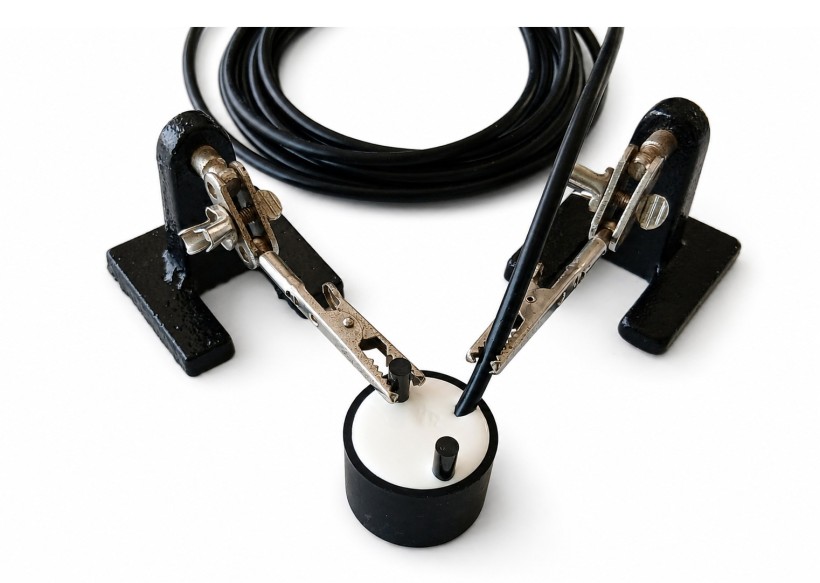
Keep the probes vertical using a third-hand tool. Using another third-hand, hold the cable about 0.5 cm from the edge of the cap. The cable tie must remain below the edge of the cap.
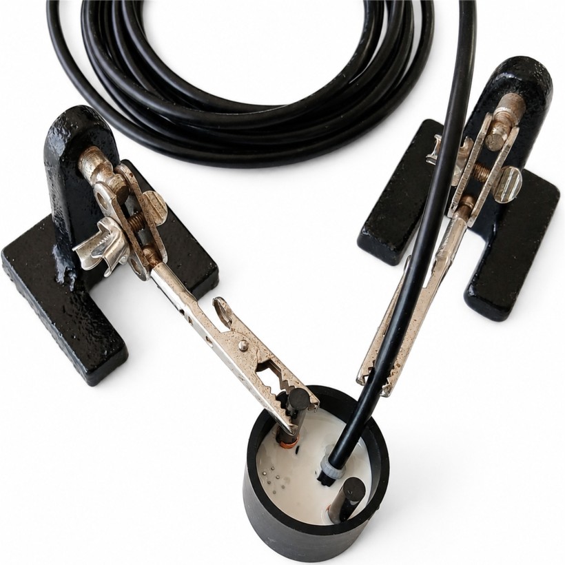
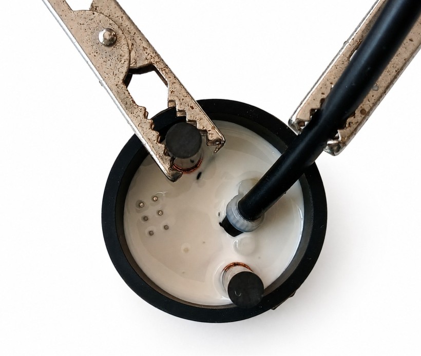
Do not skip filling the cap halfway before inserting the PCB, as testing has shown that this ensures long-term waterproofing.
Once everything is in place, fill the remaining volume of the cap with 704 silicone. Since this silicone shrinks by about 1% during curing, it is recommended to fill the cap as much as possible.
Step 6 — Curing
Allow the sensor to cure for at least 10 days before use.
Step 7 — Install
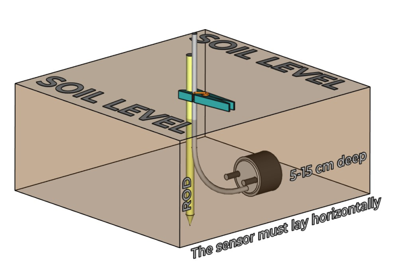
Please refer to the datasheet for detailed installation instructions.
picapot-ps100-sensor-datasheet.pdf (PDF, 609.81 KB)
Open-Source Production Resources
All project files are available under the OCL v1.1 + GAtt v1 licence.
PS100 PCB Project
https://oshwlab.com/ipposnif/project_voxlefdx
Silicone Cap
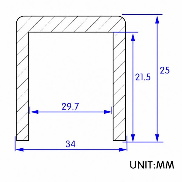
The silicone cap used in this project is the SC029.7 model manufactured by Maksey. Any cap made from the same material and with the same dimensions can be used.
Probes and Clips
The probes are made of carbon fiber and have a cylindrical shape, 30 mm in length and 5 mm in diameter.
The STL file below can be used to manufacture the clips. Two different molds are required, along with two manufacturing steps: blanking and forming.
probe_clip.stl (STL, 12.97 KB)
As an alternative to the dedicated clip, a 5 mm copper sleeve can be used. Cut the sleeve lengthwise and solder it to the two anchor pads on the PCB.